
Eight-switch non-isolated full-bridge photovoltaic grid-connected inverter and working method thereof

A full-bridge inverter circuit, non-isolated technology, used in photovoltaic power generation, conversion of AC power input to DC power output, high-efficiency power electronic conversion, etc. It can eliminate the problem of reverse recovery, realize high frequency, and suppress leakage current.

Inactive Publication Date: 2015-01-07
JIANGSU UNIV
View PDF6 Cites 4 Cited by
  • Summary
  • Abstract
  • Description
  • Claims
  • Application Information

AI Technical Summary

Problems solved by technology

The existence of switching loss limits the increase of the switching frequency of the converter, thus limiting the miniaturization and weight reduction of the converter
At the same time, when the switching tube works in hard switching, it will also generate high current and voltage change rates, resulting in large electromagnetic interference

Method used


Image

  • Eight-switch non-isolated full-bridge photovoltaic grid-connected inverter and working method thereof
  • Eight-switch non-isolated full-bridge photovoltaic grid-connected inverter and working method thereof
  • Eight-switch non-isolated full-bridge photovoltaic grid-connected inverter and working method thereof

Examples


Embodiment Construction

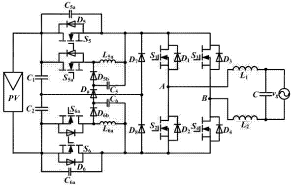
[0026] see figure 2 , the present invention includes: photovoltaic array PV, input voltage equalizing capacitor C 1 with C 2 , main switch tube S 1 - S 6 , auxiliary switching tube S 5a with S 6a , resonant capacitor C 5a with C 6a , Resonant inductance L 5a with L 6a , snubber capacitance C 5 with C 6 ,diode D 5b , D a with D 6b , clamping diode D 7 with D 8 , filter inductance L 1 with L 2 , filter capacitor C and a main switching tube S 1 , S 2 , S 3 , S 4 A full bridge inverter circuit is formed.

[0027] Among them, the input equalization capacitor C 1 with C 2 Connect in series, and then connect in parallel at both ends of the photovoltaic array PV. Input equalizing capacitor C 1 The positive terminal of the main switch tube S 5 and auxiliary switch S 5a drain, the input equalizing capacitor C 2 The negative terminal of the main switch tube S 6 and auxiliary switching tube S 6a source. main switch S 5 , S ...


PUM


Abstract

The invention discloses an eight-switch non-isolated full-bridge photovoltaic grid-connected inverter and working method thereof. A resonance capacitor C5a is connected to the two ends of the source electrode and the two ends of the drain electrode of a main switch tube S5 in parallel. A resonance capacitor C6a is connected to the two ends of the source electrode and the two ends of the drain electrode of a main switch tube S6 in parallel. The source electrode of an auxiliary switch tube S5a is connected with a resonance inductor L5a in series and then connected to the two ends of a switching tube S5 in parallel. The drain electrode of an auxiliary switch tube S6a is connected with a resonance inductor L6a in series and then connected to the two ends of a switching tube S6. A diode D5b, a diode Da and a diode D6b in the same direction are sequentially connected between the source electrode of the auxiliary switch tube S5a and the drain electrode of the auxiliary switch tube S6a. A buffering capacitor C5 is connected to the two ends of the resonance inductor L5a and the two ends of the diode D5b in parallel. A buffering capacitor C6 is connected to the two ends of the resonance inductor L6a and the two ends of the diode D6b in parallel. An auxiliary circuit is added to a high-frequency power device, flexible switching-on and flexible switching-off are achieved, the reverse recovery problem of freewheel diodes is solved at the same time, and the efficiency of the grid-connected inverter is improved as much as possible under the condition that common mode leakage current is not generated.

Description

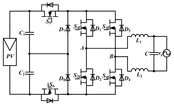
technical field [0001] The invention belongs to the technical field of power electronic power converters. Specifically, it relates to a non-isolated photovoltaic grid-connected inverter. Background technique [0002] Leakage current and efficiency are two key indicators of non-isolated photovoltaic grid-connected inverters. At present, a series of low-leakage current non-isolated photovoltaic grid-connected inverter topologies have been proposed, some of which have been widely used, such as full-bridge topology with AC bypass, H5 topology, full-bridge topology with DC bypass, diode Clamped 3-level topologies, active-clamped 3-level topologies, and more. Compared with the isolated structure, the non-isolated structure has an advantage in efficiency, but so far, some power switch tubes of the non-isolated grid-connected inverter still work in the hard switching state. Taking the six-switch transistor structure with DC bypass topology as an example, such as figure 1 shown, ...

Claims


Application Information

Patent Timeline
Patent Type & Authority Applications(China)
IPC IPC(8): H02M7/00H02M7/5387
CPCH02M7/00H02M7/5387Y02B70/10Y02E10/56
Inventor 廖志凌崔晓晨熊颖杰施卫东
Owner JIANGSU UNIV
Learn More