A horizontal heavy sludge flocculation reaction device

A reaction device, heavy technology, applied in water/sludge/sewage treatment, dehydration/drying/concentrated sludge treatment, water/sewage treatment, etc., can solve the problem of fast deposition, large amount of sludge deposition, and increased reactor load Reactor overload and other problems, to achieve the effect of simple operation management, safe and reliable operation, and avoid the release of sludge phosphorus

Active Publication Date: 2016-01-06
JIANGSU SAIOU ENVIRONMENTAL PROTECTION EQUIP
View PDF4 Cites 0 Cited by
  • Summary
  • Abstract
  • Description
  • Claims
  • Application Information

AI Technical Summary

Problems solved by technology

Because the flocs cannot be lifted in time, the sludge output of the dewatering device is not enough, and the whole dewatering device is blocked, the sludge conveying pump is damaged, the valves and pipelines are blocked, and the normal operation of the sludge dewatering device is seriously affected.
[0004] The existing technology is a square or circular vertical device, and a top-mounted coagulation reactor is installed in the device. The reaction machine is driven by a gear reducer, and the sludge in the device and the coagulant liquid are mixed and coagulated. It is used to facilitate the operation of the post-stage dehydrator; but it is used in the sludge dewatering system of large specific gravity and heavy sludge such as desulfurization treatment unit of petroleum catalytic cracking unit, stone processing industry, ceramic manufacturing industry, oil field drilling industry, special chemical catalytic industry, etc. When it is used, the sludge has the characteristics of fast sedimentation and slow coagulation reaction speed. When the conventional vertical coagulation reaction device is used, the early coagulation of the sludge is not easy to form, but once the coagulation is formed , the sludge flocs quickly sink to the bottom and cannot smoothly enter the post-stage dewatering equipment, resulting in a large amount of sludge deposition, increasing the load on the reactor and even overloading the reactor, making it impossible to effectively treat sludge

Method used


Image

  • A horizontal heavy sludge flocculation reaction device
  • A horizontal heavy sludge flocculation reaction device
  • A horizontal heavy sludge flocculation reaction device

Examples


Embodiment Construction

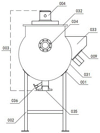
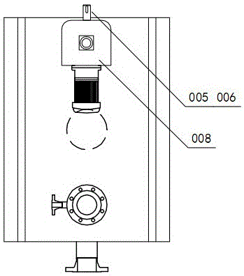
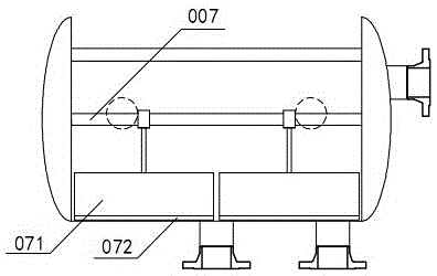
[0018] A horizontal heavy sludge flocculation reaction device, including a chassis support 001, a reaction device 003 arranged on the support 002, the reaction device 003 includes a U-shaped groove-shaped housing 031 horizontally placed on the support 002, the The upper end of the housing 031 is provided with a cover body 032, and the cover body 032 is provided with a reaction motor 004. The reaction motor 004 is a variable frequency motor, and the reaction motor 004 is connected through a reducer 005, a sprocket chain group 006 and one end of the transmission spindle 007. The transmission main shaft 007 is horizontally placed in the casing 031, and the two ends of the transmission main shaft 007 protrude from the two ends of the casing 031 and are fixed by the bearing seat 008. Two connecting plates 071 in the vertical direction are welded on the transmission main shaft 007, and the connecting plate 071 The end is connected to the push flow paddle 072, and they are arranged si...


PUM


Abstract

The invention discloses a horizontal heavy sludge flocculation reaction device comprising a chassis support and a reaction device arranged on the support, wherein the reaction device comprises a U-shaped groove-like shell horizontally arranged on the support; the upper end inside the shell is provided with a cover body on which a reaction motor is arranged; the reaction motor is in transmission connection with one end of a main transmission shaft through a speed reducer and a chain wheel-chain group; the main transmission shaft is horizontally arranged in the shell; two ends of the main transmission shaft extend out of two ends of the shell and are fixed by using bearing blocks; at least one connecting plate arranged in the vertical direction is welded on the main transmission shaft; the tail end of the connecting plate is connected with a flow pushing paddle board; the side of the shell is provided with an inclined flocculate discharging chute which is welded on the shell and is internally provided with a mud cut-off plate; an overflow opening is formed in the end face of the shell; and a sewage inlet and a flushing water inlet are formed in the bottom of the shell. The horizontal heavy sludge flocculation reaction device is novel in structure, simple and convenient to maintain and capable of avoiding the condition that sludge is deposited and accumulated at the bottom after being flocculated.

Description

technical field [0001] The invention relates to a heavy sludge flocculation reaction device, in particular to a horizontal heavy sludge flocculation reaction device. Background technique [0002] With the increasingly stringent requirements of the country for environmental protection and the continuous development of sludge dewatering methods, the types of sludge being processed are becoming more and more diverse and complex. [0003] Although there are various types of sewage dehydration devices today, most of them treat relatively small proportions of sewage. Once it encounters sludge with a large specific gravity, the sewage flocs will quickly deposit on the bottom of the reaction vessel. Due to the inability to lift the flocs in time, the sludge output of the dewatering device is not enough, and the whole dewatering device is blocked, the sludge conveying pump is damaged, the valves and pipelines are blocked, and the normal operation of the sludge dewatering device is s...

Claims


Application Information

Patent Timeline
Patent Type & Authority Patents(China)
IPC IPC(8): C02F11/14
CPCC02F11/14C02F2201/002
Inventor 吴水华吴征王欢曹俊钱俊戴超袁声明
Owner JIANGSU SAIOU ENVIRONMENTAL PROTECTION EQUIP
Why Eureka
Try Eureka