Energy-saving annealing furnace

An annealing furnace and furnace body technology, applied in the field of energy-saving annealing furnaces, can solve the problems of lowering the temperature of the annealing furnace, poor heat preservation effect, and high energy loss, and achieve the effects of preventing excessive pressure, safe and reliable use, and promoting gasification and volatilization

Inactive Publication Date: 2015-01-21
长沙硬承环保科技有限公司
View PDF5 Cites 9 Cited by
  • Summary
  • Abstract
  • Description
  • Claims
  • Application Information

AI Technical Summary

Problems solved by technology

However, existing annealing furnaces generally have disadvantages such as poor heat insulation effect, high energy consumption, and rapid heat loss. The cotton is directly fixed on the outer wall panel, and the insulation wall made of refractory bricks is bulky and has poor insulation effect; the stainless steel lining and insulation cotton are directly fixed on the outer wall. Although this structure can also play a certain role in insulation, due to the anchorage The nails are in direct contact with the outer wall panels, and the heat in the furnace will be directly transferred to the outer wall panels along with the anchor nails. When the anchor nails are dense, it will also cause a large amount of heat dissipation on the insulation wall. At the same time, the hot air in the furnace will pass through the insulation cotton. The heat transfer occurs directly between the gap and the outer wall of the insulation wall, which affects the insulation effect of the insulation wall and reduces the temperature in the annealing furnace; 2. The heating system mainly adopts the method of heating the furnace wall with resistance wires or natural gas combustion to heat the air and then passes the hot air through In the way of heating in the furnace, the former consumes a lot of power when the resistance wire is burned, and the energy saving effect is not obvious; the exhaust gas will take away a lot of heat when the latter is burned, and the energy loss is large.

Method used


Image

  • Energy-saving annealing furnace
  • Energy-saving annealing furnace
  • Energy-saving annealing furnace

Examples


Embodiment Construction

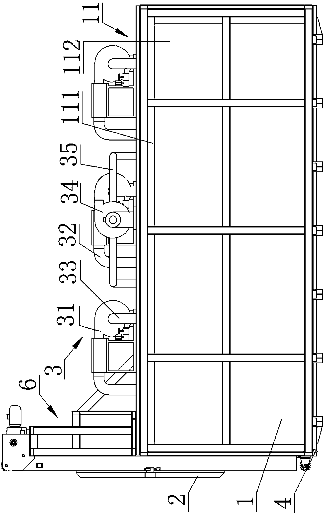
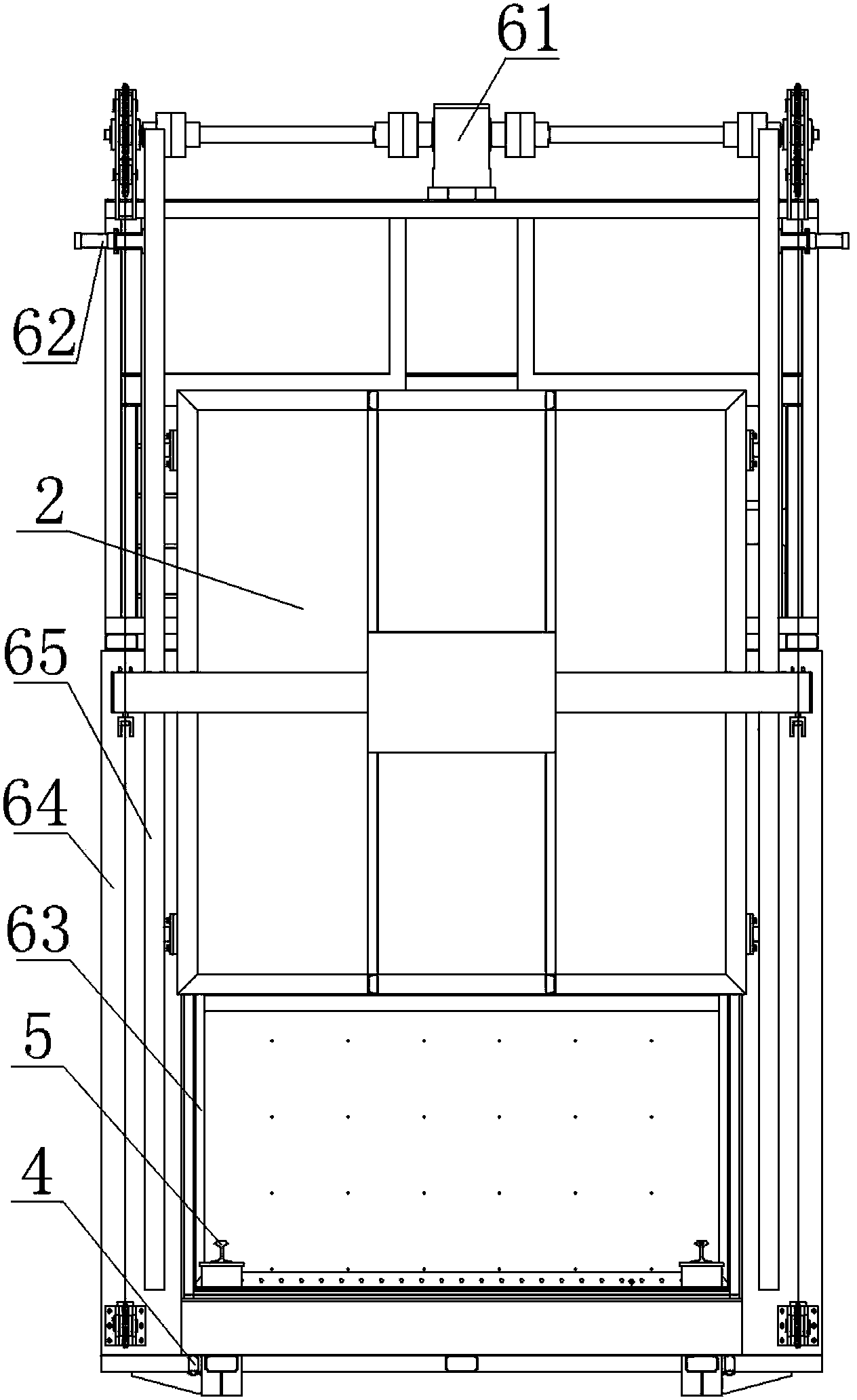
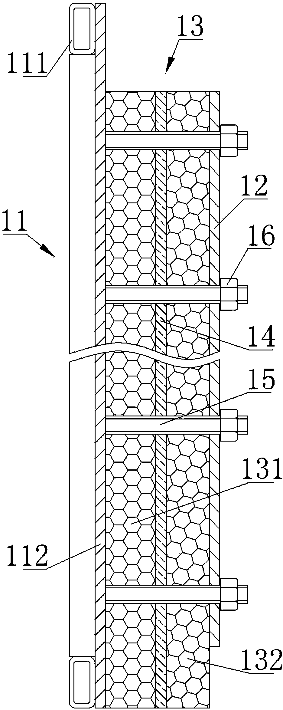
[0025] From Figure 1 to Figure 8 It can be seen that the energy-saving annealing furnace of the present invention includes a furnace body, a circulating heating system 3, a temperature control detection device 4 and a track 5, the furnace body includes a heat-insulating wall 1 and a furnace door 2, and the heat-insulating wall 1 includes an outer wall panel 11, Inner wallboard 12, thermal insulation cotton 13, thermal insulation aluminum foil 14, several screw rods 15 and several nuts 16 filled between the outer wallboard 11 and inner wallboard 12, thermal insulation cotton 13 includes a first thermal insulation cotton layer 131 and a second thermal insulation cotton layer 131 The cotton layer 132, the furnace door 2 is installed on the insulation wall 1 through the lifting device 6, the circulation heating system 3 includes a heating fan 31, a hot air pipe 32, a return air pipe 33, a negative pressure fan 34 and a negative pressure air pipe 35, and the outer wall The board 1...


PUM


Abstract

The invention discloses an energy-saving annealing furnace which comprises a furnace body, the furnace body comprises a thermal insulating wall and a furnace door, the thermal insulating wall comprises an external wall board, an internal wall board and thermal insulating cotton filled between the external wall board and the internal wall board, and the furnace door is mounted on the thermal insulating wall through a lifting device. The energy-saving annealing furnace further comprises a circulation heating system, the thermal insulating wall also comprises a thermal-insulating aluminum foil, a plurality of screw rods and a plurality of nuts, the circulation heating system comprises a heating fan, a hot air pipe, an air return pipe, a negative pressure fan and a negative pressure air pipe, and the thermal insulating cotton comprises a first thermal insulating cotton layer and a second thermal insulating layer. The energy-saving annealing furnace has the advantages of simple structure, convenience in operation, good energy-saving effect, safety and reliability in use and longer service life.

Description

technical field [0001] The invention relates to an energy-saving annealing furnace. Background technique [0002] The annealing furnace is a metal heat treatment process in which metal materials or parts are slowly heated to a certain temperature in different annealing furnaces, kept for a period of time, and then cooled at an appropriate speed. The purpose is to soften the material or workpiece after casting, forging, welding or cutting, reduce the hardness, improve plasticity and toughness, homogenize the chemical composition, remove residual stress, or obtain the expected physical properties. [0003] The continuous bright annealing furnace is mainly used for continuous bright annealing of different specifications of copper straight pipes (rods), steel pipes, aluminum pipes or disks under controlled atmosphere. With the extensive use of aluminum products such as aluminum foil and aluminum coils in daily life, the lightweight development of automobiles and other equipment...

Claims


Application Information

Patent Timeline
Patent Type & Authority Applications(China)
IPC IPC(8): C21D1/26
CPCC21D1/26
Inventor 阙先进刘玖鑫周宇张浩然
Owner 长沙硬承环保科技有限公司
Why Eureka
Try Eureka