Ion sputtering film-plating machine

An ion sputtering and coating machine technology, applied in the field of ion sputtering coating machine, can solve the problems of poor coating surface quality, difficult control of film thickness uniformity, small effective coating area, etc., so as to achieve film thickness uniformity control and increase Effective coating area, improving the effect of coating surface quality

Active Publication Date: 2015-01-21
杰莱特(苏州)精密仪器有限公司
View PDF3 Cites 8 Cited by
  • Summary
  • Abstract
  • Description
  • Claims
  • Application Information

AI Technical Summary

Problems solved by technology

[0005] The purpose of the present invention is to solve the technical problems of the existing ion sputtering coating machine that the effective coating area is small, the uniformity of the film thickness is not easy to control, and the surface quality of the coating is poor, and to provide a coating with a large coating area and easy control of the uniformity of the film thickness. Ion sputtering coating machine with high coating surface quality

Method used


Image

  • Ion sputtering film-plating machine
  • Ion sputtering film-plating machine
  • Ion sputtering film-plating machine

Examples


Embodiment 1

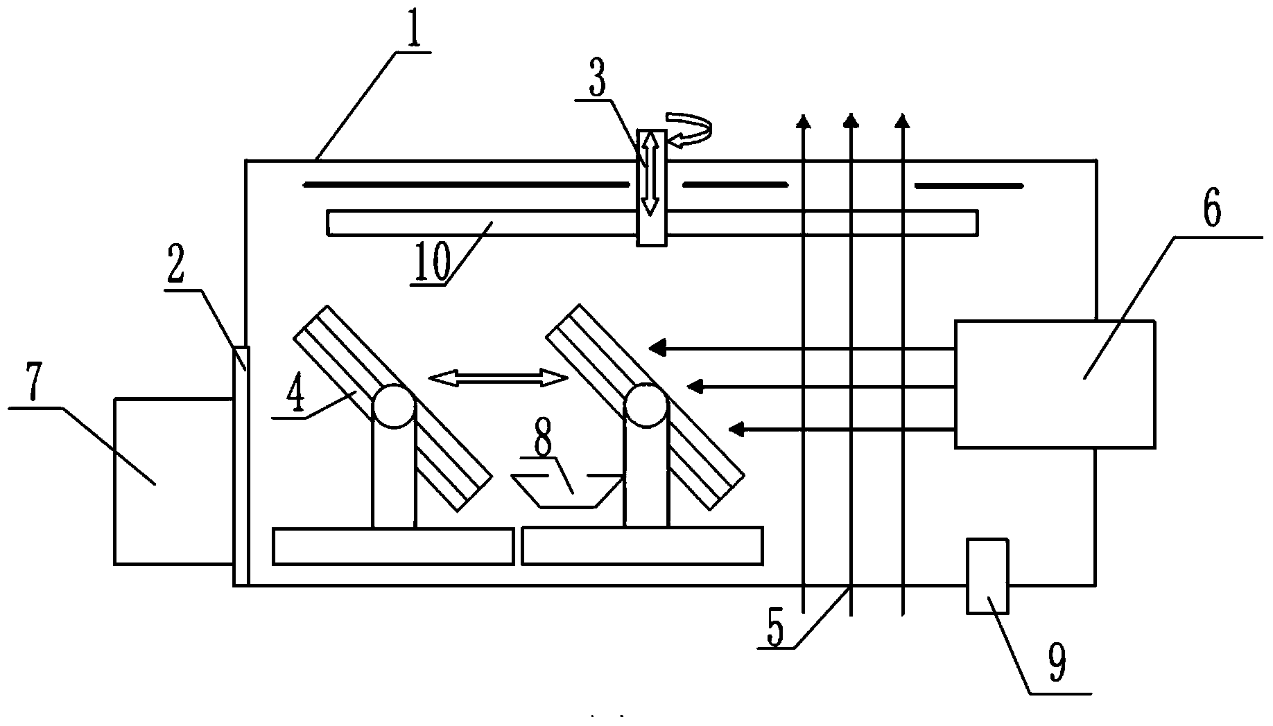
[0026] Such as figure 1 , figure 2 , Figure 5 and Figure 6 As shown, the ion sputtering coating machine in the present embodiment comprises a vacuum chamber 1, a large valve 2, an ion source 6, an observation window 5 of a multi-beam optical film thickness meter, a high vacuum pump 7, a heater 8 and ion neutralization device 9, wherein: it also includes a moving coating target 4 and a rotating substrate support 3, the moving coating target 4 is located at the bottom of the vacuum chamber 1 and is positioned under the coating fixture 10 in the rotating substrate support 3, and the moving coating target 4 can be positioned at the bottom of the vacuum chamber 1 The vacuum chamber 1 moves linearly, and the rotating substrate support 3 is set above the vacuum chamber 1 and can move up and down. On the rotation radius, the monitoring points 23 arranged on different rotation radii of the rotating substrate holder 3 can be observed in real time. The large valve 2 and the ion so...

Embodiment 2

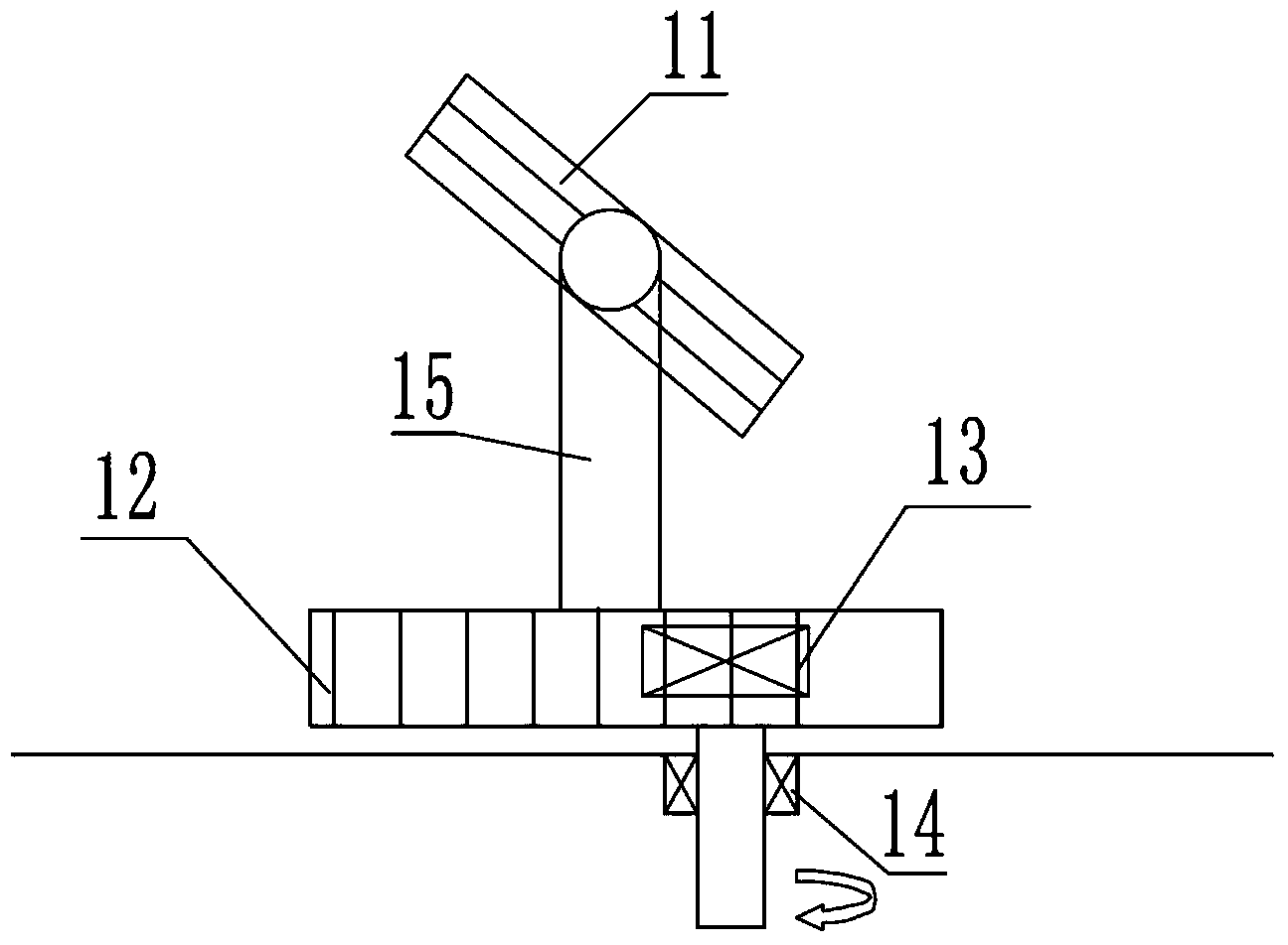
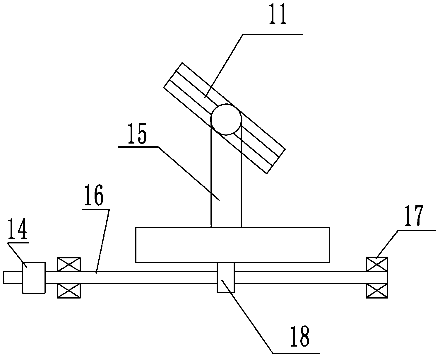
[0028] Such as figure 1 , image 3 , Figure 5 and Figure 6 As shown, in the ion sputtering coating machine in this embodiment, the linear motion mechanism is composed of a screw 16, a nut 18, a bearing 17 and a magnetic fluid rotary seal 14, and the nut 18 is arranged at the bottom of the target support 15 Leading screw 16 is located in screw nut 18 and is installed on the bottom surface of vacuum chamber 1 through bearing 17. One end of leading screw 16 is connected with magnetic fluid rotary seal 14, and magnetic fluid rotary seal 14 is located on vacuum chamber 1.

[0029] The ion sputter coating machine in this embodiment is different from the linear motion mechanism in the ion sputter coating machine in embodiment 1 except that the linear motion mechanism is the same as that of the ion sputter coating machine in embodiment 1. .

Embodiment 3

[0031] Such as figure 1 , Figure 4 , Figure 5 and Figure 6 As shown, in the ion sputtering coating machine in this embodiment, the linear motion mechanism is a linear motor 19, the primary of the linear motor 19 is arranged at the bottom of the target support 15, and the secondary of the linear motor 19 is arranged in the vacuum chamber 1 on the bottom surface.

[0032] The ion sputter coating machine in this embodiment is different from the linear motion mechanism in the ion sputter coating machine in embodiment 1 except that the linear motion mechanism is the same as that of the ion sputter coating machine in embodiment 1. .


PUM


Abstract

The invention relates to an ion sputtering film-plating machine, which belongs to an ion sputtering vacuum film-plating facility. The ion sputtering film-plating machine is designed for mainly solving the technical problems that existing ion sputtering film-plating machines are small in effective film-plating area, not easily controlled in film thickness uniformity, and poor in surface quality of plated films. The technical scheme of the invention is as follows: the ion sputtering film-plating machine comprises a vacuum chamber, a large valve, an ion source, an observation window of a multi-beam optical film thickness gauge, a high-vacuum pump, a heater, an ion neutralizer, a movable film-plating target and a rotating substrate holder, wherein the movable film-plating target is arranged at the bottom of the inside of the vacuum chamber and located below a film-plating fixture in the rotating substrate holder, the movable film-plating target can carry out a linear motion in the vacuum chamber, the rotating substrate holder is arranged on the upside of the inside of the vacuum chamber and can move upwards and downwards, and the observation window of the multi-beam optical film thickness gauge is arranged on the outer wall of the vacuum chamber and located on the rotating radius of the rotating substrate holder.

Description

technical field [0001] The invention relates to an ion sputtering coating machine, which belongs to an ion sputtering vacuum coating equipment. Background technique [0002] The ion sputtering coating machine is a gas molecule in the ion source, which forms positive ions and electrons after high-voltage ionization. The positive ions are accelerated under the action of an electric field and bombard the target with high kinetic energy, so that the atomic energy of the target increases and detaches from the surface to form sputtering. layer, deposited on a glass substrate to form an optical film. [0003] In the process of ion sputtering to deposit optical films, the factors that affect the film deposition rate mainly include the beam current, beam pressure, vacuum degree and temperature of the ion source; however, various physical states of the target, substrate and fixture also affect the film deposition rate. A factor that cannot be ignored. [0004] In the current structu...

Claims


Application Information

Patent Timeline
Patent Type & Authority Applications(China)
IPC IPC(8): C23C14/46
CPCC23C14/34C23C14/3407C23C14/547
Inventor 张殷邓琪张小飞王静辉吕子啸
Owner 杰莱特(苏州)精密仪器有限公司
Why Eureka
Try Eureka