Data converting method of intelligent vision numerical control system

A technology of data transformation and numerical control system, applied in the direction of digital control, electrical program control, etc., can solve the problems of low efficiency, high quality requirements of personnel, and large consumption of development resources, so as to achieve the effect of convenient data and convenient development

Active Publication Date: 2015-01-21
JINAN UNIVERSITY
View PDF8 Cites 5 Cited by
  • Summary
  • Abstract
  • Description
  • Claims
  • Application Information

AI Technical Summary

Problems solved by technology

This development mode requires high personnel quality, consumes a lot of development r

Method used


Image

  • Data converting method of intelligent vision numerical control system
  • Data converting method of intelligent vision numerical control system
  • Data converting method of intelligent vision numerical control system

Examples


Embodiment Construction

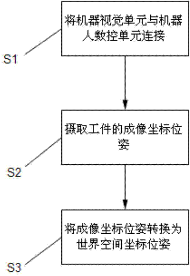
[0037] see figure 1 , which is a flow chart of the data conversion method of the visual intelligent control system of the present invention.

[0038] A data conversion method of a visual intelligent numerical control system, the visual intelligent numerical control system includes a machine vision unit, a numerical control unit and a pose standard module. The data conversion method includes the following steps:

[0039] S1: Connect the machine vision unit with the robot numerical control unit;

[0040] S2: Capture the imaging coordinate pose of the workpiece through the machine vision unit, and send the imaging coordinate data to the pose standard module;

[0041] S3: The pose standard module converts the imaging coordinate pose into a world space coordinate pose, and sends it to the numerical control unit.

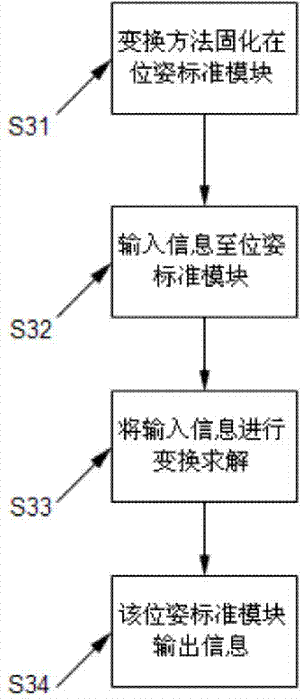
[0042] see figure 2 , which is the pose transformation flow chart of the pose standard module. Further, the step S3 specifically includes the following steps:

[0...


PUM


Abstract

The invention relates to a data converting method of an intelligent vision numerical control system. The data converting method comprises the following steps that a machine vision unit is connected with a robot numerical control unit; an imaging coordinate pose of a workpiece is extracted through the machine vision unit and sent to a pose standard module; the pose standard module converts the imaging coordinate pose into a world space coordinate pose, and sends the world space coordinate pose to the numerical control unit. Compared with the prior art, a processing algorithm is fixed into a vision sub-system and a numerical control sub-system, and specifically, the processing algorithm is fixed to the pose standard module. Thus, when developing projects, an application engineer does not need to concern the calculation process with high theoretical property and only needs to pay attention to the application development of the numerical control system and parameter setting of a robot body and the machine vision unit, the requirement for core algorithm confidentiality is met, and the development period is shortened.

Description

technical field [0001] The invention belongs to the field of advanced manufacturing and robot control, and relates to a data transformation method, in particular to a data transformation method of a visual intelligent numerical control system. Background technique [0002] The application of machine vision in the field of robot control is an important milestone in the industrial application of robots. The application of independent industrial robots is subject to multiple constraints of site, processing target, processing method and development efficiency, and the application and promotion are narrow and limited. CNC equipment or industrial robots integrated with a visual intelligent CNC system can perform more complex and delicate actions in a larger workspace, locate the position of the workpiece in the plane, transform the coordinates of the workpiece to the robot coordinates, and then the robot performs the grabbing action. [0003] The machine vision system can be used...

Claims


Application Information

Patent Timeline
IPC IPC(8): G05B19/18
CPCG05B19/19
Inventor 王高柳宁叶文生
Owner JINAN UNIVERSITY
Why Eureka
Try Eureka