Intensity-correlation star sensor

An intensity correlation and star sensor technology, applied in the field of star sensors, can solve problems such as complex single star recognition and attitude calculation, limited stability of image resolution tube simulation, large mass and volume of star sensors, etc., and achieve fast detection speed , easy engineering implementation, and improved detection sensitivity

Active Publication Date: 2015-01-28
BEIJING INST OF AEROSPACE CONTROL DEVICES
View PDF5 Cites 8 Cited by
  • Summary
  • Abstract
  • Description
  • Claims
  • Application Information

AI Technical Summary

Problems solved by technology

The early star sensors used the image resolution tube as the detection device. This kind of structure device is relatively simple, and it is mainly used in ground instruments such as large astronomical telescopes and missile guidance. However, due to the limitation of the simulation stability of the image resolution tube itself, it cannot meet the requirements of high precision Require
[0003] In 1974, the Jet Laboratory (JPL) of the United States began to develop the second-generation star sensor---CCD star sensor. Compared with the star sensor of the first stage, the CCD star sensor has high resolution and radiation resistance. However, its relative field of view is small. Although the measurement accuracy of a single star is high, the recognition and attitude calculation of a single star are too complicated, and the quality and volume of the star sensor are relatively large; until the last century In the 1990s, in order to meet the strict requirements of aerospace devices, based on the substantial improvement of optics, precision machinery, electronics and computer technology, the second generation of CCD star sensors began to appear. The new generation of star sensors has a large field of view, star Small table and other advantages, more independent navigation function
At this stage, CCD star sensors are widely used in domestic and international markets, but regardless of the first generation or second generation star sensors, CCD star sensors are based on the development level of CCD cameras, and are limited by parameters such as the number of CCD pixels.

Method used


Image

  • Intensity-correlation star sensor
  • Intensity-correlation star sensor

Examples


Embodiment Construction

[0018] In the following, the intensity-associated star sensor according to the present invention will be described in further detail with reference to the drawings and specific embodiments.

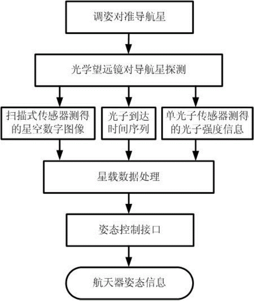
[0019] Such as figure 1 As shown, the intensity-related star sensor according to the present invention includes a first light shield, a second light shield, a first optical telescope, a second optical telescope, a scanning sensor, a single photon sensor, an electronic readout device, and a video processing device , On-board time-frequency device, on-board data processing equipment, and attitude control interface.

[0020] The first light shield and the second light shield are respectively installed in front of the first optical telescope and the second optical telescope to block stray light from non-target stars (for example, the sun, moon, and earth), so as to greatly reduce the amount of light entering the optical telescope. Noise: The first optical telescope and the second optical telescope...


PUM


Abstract

The invention provides an intensity-correlation star sensor which comprises a first lens hood, a second lens hood, a first optical telescope, a second optical telescope, a scanning type sensor, a single photon sensor, electronics read-out equipment, video processing equipment, a satellite-borne time-frequency device, satellite-borne data processing equipment and an interface. By using detection signals of two paths of optical detection systems, the obtained two paths of electric signals are subjected to time synchronization by using the satellite-borne time-frequency device, and are subjected to intensity-correlation signal processing in the satellite-borne data processing equipment. Therefore, on the basis of keeping an integral appearance shape of an optical system of an original star sensor unchangeable, an internal structure is locally regulated, and the engineering realization is easy. The starry sky is imaged by using an intensity-correlation method in a quantum imaging technology, and is searched by using the scanning type sensor; the single photon is used in the other path, relatively dark star bodies are relatively easily detected, and the detection sensitivity is greatly improved.

Description

Technical field [0001] The invention relates to a star sensor based on quantum imaging technology, belonging to the field of star sensors. Background technique [0002] The star sensor was first successfully developed in the 1950s and was mainly used in aircraft and missile navigation. So far, it has experienced three stages of development, and has been widely used in aerospace devices such as missiles, aircraft, spacecraft, satellites, etc., involving multiple measurement fields. Comparing several commonly used sensors, the star sensor has the advantages of high accuracy, light weight, low power consumption, no drift, and multiple working modes. Early star sensors used a resolution tube as a detector. This structure is relatively simple and is mainly used in ground instruments such as large astronomical telescopes and missile guidance. However, due to the limitation of the analogue stability of the resolution tube itself, it cannot meet high-precision Claim. [0003] In 1974, J...

Claims


Application Information

Patent Timeline
Patent Type & Authority Applications(China)
IPC IPC(8): G01C21/02
CPCG01C21/025
Inventor 杨然王增斌杨文良王俊张安宁
Owner BEIJING INST OF AEROSPACE CONTROL DEVICES
Why Eureka
Try Eureka