Insulated electric wire and motor

A technology of insulated wires and insulating layers, applied in the direction of insulated cables, insulators, insulated conductors, etc., can solve the problems of damaged insulating layers, insufficient wear resistance of the insulating layer surface, etc., and achieve the effect of high damage resistance

Active Publication Date: 2015-01-28
ESSEX FURUKAWA MAGNET WIRE LLC
View PDF11 Cites 3 Cited by
  • Summary
  • Abstract
  • Description
  • Claims
  • Application Information

AI Technical Summary

Problems solved by technology

In particular, the insulated electric wire described in Patent Document 3 has a problem that the surface of the insulating layer has insufficient wear resistance, so that the insulating layer is easily damaged when used as a winding wire.

Method used


Image

  • Insulated electric wire and motor
  • Insulated electric wire and motor
  • Insulated electric wire and motor

Examples


Embodiment 1

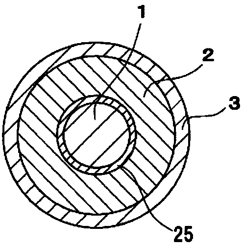
[0115] Made in the following way figure 2 insulated wire shown. First, the foamed polyamide-imide varnish for forming the foamed insulating layer 2 was prepared as follows. Put HI-406 (trade name, manufactured by Hitachi Chemical Co., Ltd.) in a 2L separable flask, and add triethylene glycol dimethyl ether and diethylene glycol dibutyl ether as bubble forming agents to the solution, and then use dimethyl Diluted with sulfoxide, thus obtained.

[0116] In addition, HI-406 was used as the polyamide-imide varnish for forming the inner non-foamed insulating layer for forming the inner non-foamed insulating layer 25 . This varnish was prepared as a 30% by mass solution using NMP as a solvent.

[0117] Each varnish was applied by dip coating, and the coating amount was adjusted by a die. Specifically, the prepared polyamideimide varnish for forming an inner non-foamed insulating layer was coated on a copper conductor 1 with a circular cross-section of 1.0 mmφ, and fired at a fu...

Embodiment 2

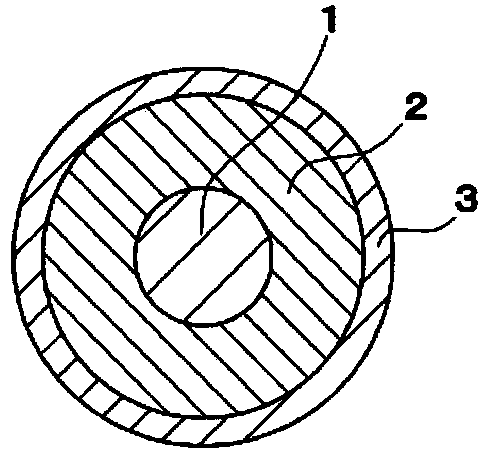
[0120] Made in the following way figure 1 insulated wire shown. The outer peripheral surface of a copper conductor 1 with a circular cross-section of 1.0 mmφ is directly coated with the foamed polyamideimide varnish prepared in Example 1, and fired at a furnace temperature of 510° C. to obtain a thickness formed. A molded body (undercoated line) of the foamed insulating layer 2 of 20 μm. Next, HI-406 (trade name, manufactured by Hitachi Chemical Co., Ltd.) was fired at a furnace temperature of 510°C so as to have a thickness of 80 μm. The undercoating line was coated with HI-406, and then heated to 600° C. in a tubular furnace ( Koyo Thermo Systems Co., Ltd.; KTF030N1 (trade name)) was reheated for 20 seconds to form the outer non-foamed insulating layer 3 . The insulated electric wire of Example 2 was manufactured in the above-mentioned manner.

Embodiment 3

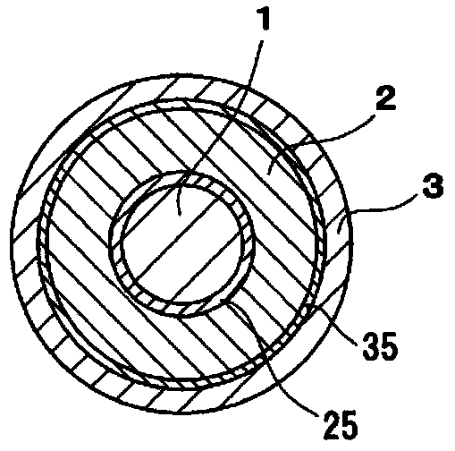
[0122] Made in the following way Figure 5 insulated wire shown. First, the foamed polyimide varnish for forming the foamed insulating layer 2 was prepared as follows. A solution was prepared by adding Uimide (NMP solution of 25% by mass of resin component) (manufactured by Unitika, trade name) to a 2L separable flask, and adding NMP, DMAC, and tetraethylene glycol dimethyl ether as a solvent.

[0123] The polyimide varnish for forming the inner non-foamed insulating layer used to form the inner non-foamed insulating layer 25 was prepared using Uimide and adding DMAC as a solvent to the resin.

[0124] In 1.8 * 3.4mm (thickness * width) and the chamfering radius r of four corners is the outer peripheral surface of copper conductor 1 of 0.3mm flat coating inside non-foaming insulating layer formation polyimide varnish, it is in furnace temperature Firing was performed at 520° C. to form inner non-foamed insulating layer 25 with a thickness of 4 μm. Next, the prepared foamed ...


PUM

PropertyMeasurementUnit
glass transition temperatureaaaaaaaaaa

Abstract

Provided is an insulated electric wire comprising a conductor, an insulation layer including a foam heat-curable resin and which covers the outer circumferential surface of the conductor, and an outside non-foam insulation layer that covers the outer circumferential surface of the insulation layer. The thickness deformation rate of the insulation layer when a pressure of 1 MPa is applied at 25°C is 15%-50%. The pencil hardness of the outside non-foam insulation layer is at least 4H and the ratio between the insulation layer thickness and the outside non-foam insulation layer thickness is 20:80-80:20. Also provided is a motor having this insulated electric wire wound around a stator slot, in a state in which pressure is applied in the direction in which the outer diameter of the insulated electric wire decreases, and the thickness of the insulation layer is reduced.

Description

technical field [0001] The present invention relates to insulated wires and electric motors. Background technique [0002] Frequency converters (inverters) are installed on many electrical equipment as effective variable speed control devices. However, the inverter performs switching at several kHz to several tens of kHz, and a surge voltage is generated in response to these pulses. For such an inverter surge, reflection occurs at a discontinuous point of impedance within the transmission body, such as the beginning or end of the connected wiring, and as a result, a maximum inverter surge is applied. 2 times the voltage of the output voltage. In particular, the output pulses generated by high-speed conversion elements such as IGBTs have a high voltage steepness, so even if the connecting cable is shortened, the surge voltage is high, and the voltage attenuation caused by the connecting cable is also small. The output voltage is nearly 2 times the voltage. [0003] In inv...

Claims


Application Information

Patent Timeline
Patent Type & Authority Applications(China)
IPC IPC(8): H01B7/02H01F5/06H02K3/32
CPCH01B7/02H02K3/30H02K3/32H01F5/06H01B3/308H01B7/1805H02K3/48
Inventor 大矢真武藤大介富泽惠一
Owner ESSEX FURUKAWA MAGNET WIRE LLC
Why Eureka
Try Eureka