
Device for using flue gas waste heat of rotary cement kiln to preheat air

A cement rotary kiln and flue gas waste heat technology, applied in the field of preheating air devices, can solve the problems of unsuitable combustion air preheating, large blower power increase, and affecting combustion efficiency, so as to facilitate temperature rise and suppress ash Resistance, the effect of improving heat transfer efficiency

Inactive Publication Date: 2015-02-04
UNIV OF SCI & TECH LIAONING
View PDF5 Cites 3 Cited by
  • Summary
  • Abstract
  • Description
  • Claims
  • Application Information

AI Technical Summary

Problems solved by technology

Some cement kiln waste gas temperature can reach 600 ℃, the waste gas is directly discharged into the atmosphere, wasting a lot of energy and polluting the air
In the pulverized coal combustion process, a large amount of air needs to be blown in, and the low temperature of the blown air will affect the combustion efficiency
Preheating the air by using the waste heat of the flue gas is a better energy-saving method. Although the existing air preheater has a high heat transfer efficiency, it has a large air flow resistance and requires a large increase in the power of the blower, which is not suitable for cement rotation. The required combustion air preheating of the kiln

Method used


Image

  • Device for using flue gas waste heat of rotary cement kiln to preheat air
  • Device for using flue gas waste heat of rotary cement kiln to preheat air
  • Device for using flue gas waste heat of rotary cement kiln to preheat air

Examples


Embodiment Construction

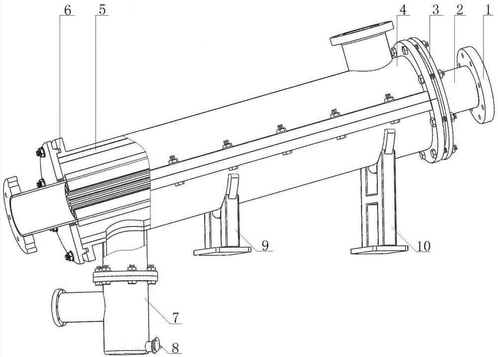
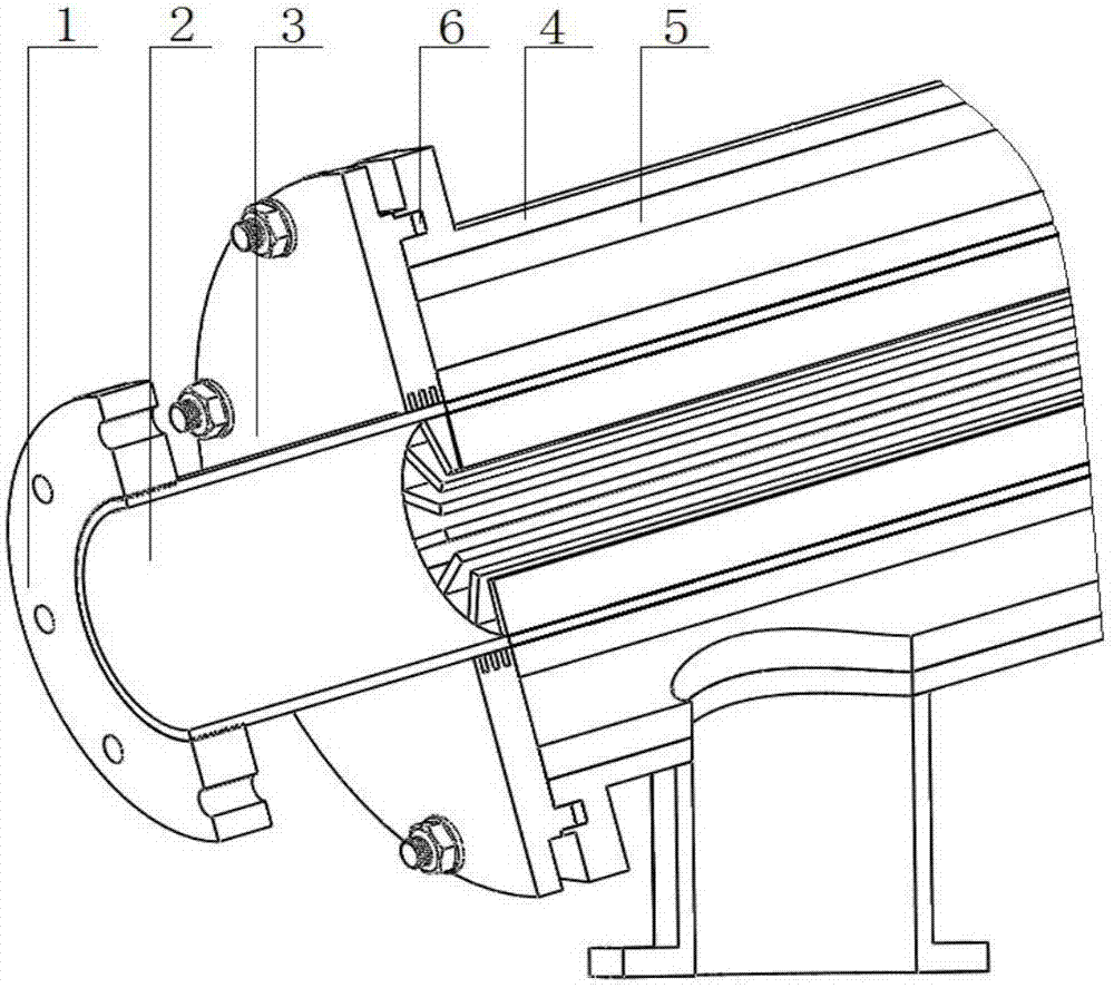
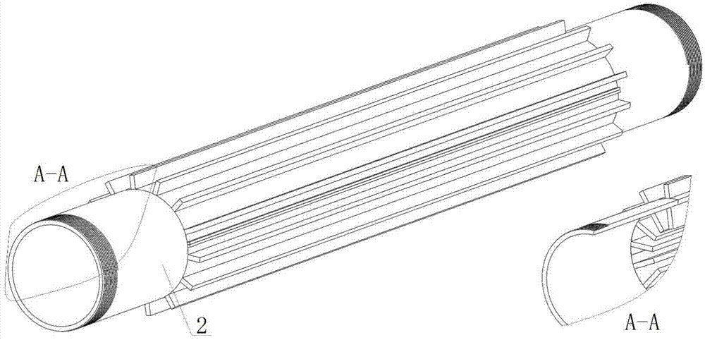
[0019] Such as Figure 1~5 As shown, a device for preheating air by using the waste heat of flue gas from a cement rotary kiln, the device includes: threaded flange 1, ribbed pipe 2, flange 3, shell 4, refractory lining 5, sealing ring 6, gravity dust removal Joint 7, dust removal end cover 8, low support 9 and high support 10, the shell 4 is formed by two semicircular steel shells connected by bolts, and its inner surface is provided with a refractory lining 5, the refractory lining material is Waxstone brick; the ribbed tube 2 is inside the shell 4, and the ribbed tube 2 is welded by two semicircular ring-shaped steel structures and two sections of threaded plain tubes, the two ends of the ribbed tube are bare tubes, and the The pipe passes through the flange with holes and is screwed with the threaded flange. The inner and outer surfaces of the ribbed pipe 2 are welded with 14 straight fins along the axial direction. The air flows inside the ribbed pipe 2. The outer surface...


PUM


Abstract

The invention discloses a device for using flue gas waste heat of a rotary cement kiln to preheat air, so as to effectively improve the heat energy utilization rate of the rotary cement kiln. The device comprises a threaded flange, a ribbed pipe, a flange, a shell, a refractory lining, a sealing ring, a gravity dust removal joint, a dust removal end cover, a low support and a high support. The device for using flue gas waste heat of the rotary cement kiln to preheat air has the advantages that the thermal efficiency is higher and the medium flowing resistance is smaller; since the flue gas and the air flow in reverse directions, reverse heat exchange is realized; the arranged refractory lining has the effect of heat preservation and heat storage, the temperature of the refractory lining is increased, the surface of the high-temperature refractory lining realizes radiative heat transfer to the ribbed pipe and the heat supply of the ribbed pipe is effectively supplemented; since fourteen long strip-shaped straight ribs are arranged on the inner and outer walls of the ribbed pipe, the ribs increase the convectional heat exchange area and the heat transfer is enhanced; the device also has a dust removal function; since the shell is embedded into two supports at different heights through arc-shaped convex blocks, the entire device and the horizontal plane form a certain inclination angle; since the gravity dust removal joint is arranged at a flue gas outlet of the steel shell, the dust removal is facilitated.

Description

technical field [0001] The invention relates to a flue gas waste heat utilization device, in particular to a device for preheating air by utilizing the waste heat of flue gas from a cement rotary kiln. Background technique [0002] In the industrial production process of cement rotary kiln, when pulverized coal is used as fuel, a large amount of pulverized coal will be consumed for combustion, and a large amount of high-temperature flue gas will be produced at the same time. The temperature of some cement kiln waste flue gas can reach 600°C. These waste flue gases are directly discharged into the atmosphere, wasting a lot of energy and polluting the air. In the process of pulverized coal combustion, a large amount of air needs to be blown in, and the low temperature of the blown air will affect the combustion efficiency. Preheating the air by using the waste heat of the flue gas is a better energy-saving method. Although the existing air preheater has a high heat transfer e...

Claims


Application Information

Patent Timeline
Patent Type & Authority Applications(China)
IPC IPC(8): F27D17/00F23L15/00
CPCY02E20/34Y02P10/25
Inventor 马学东李玲玲张艳兵董彦博袁帅方振丰
Owner UNIV OF SCI & TECH LIAONING
Learn More