
Flue gas desulfurization wastewater waste catalyst separation process

A waste catalyst and desulfurization wastewater technology, applied in chemical instruments and methods, water/sewage multi-stage treatment, water/sludge/sewage treatment, etc., can solve the problem of harsh working environment, heavy transportation load, large amount of discharged wastewater, etc. problems, achieve complete solid-liquid separation, reduce equipment footprint, and shorten residence time

Active Publication Date: 2015-02-11
LUOYANG PETROCHEMICAL ENG CORP SINOPEC +1
View PDF4 Cites 21 Cited by
  • Summary
  • Abstract
  • Description
  • Claims
  • Application Information

AI Technical Summary

Problems solved by technology

There are the following problems in doing so: first, the amount of wastewater discharged outside is large; second, the size of the equipment is large, the floor area is large, and the one-time investment is high; third, the flocculation effect is poor, a large amount of spent catalyst is difficult to settle, and the total suspension It is difficult to ensure the content of particulate matter; fourth, the discharged waste catalyst particles have a large water content, usually reaching a moisture content of 70-80 wt%, which greatly increases the transportation load
Although this patent guarantees that the suspended solids in the discharged wastewater meet the standards, there are still problems such as large waste liquid discharge. The thick slag is treated with a filter box for static filtration. The equipment not only occupies a large area, but also works intermittently. The waste slag is processed manually. , the working environment is harsh, and the spent catalyst particles taken outside have high water content

Method used


Image

  • Flue gas desulfurization wastewater waste catalyst separation process

Examples


Embodiment Construction

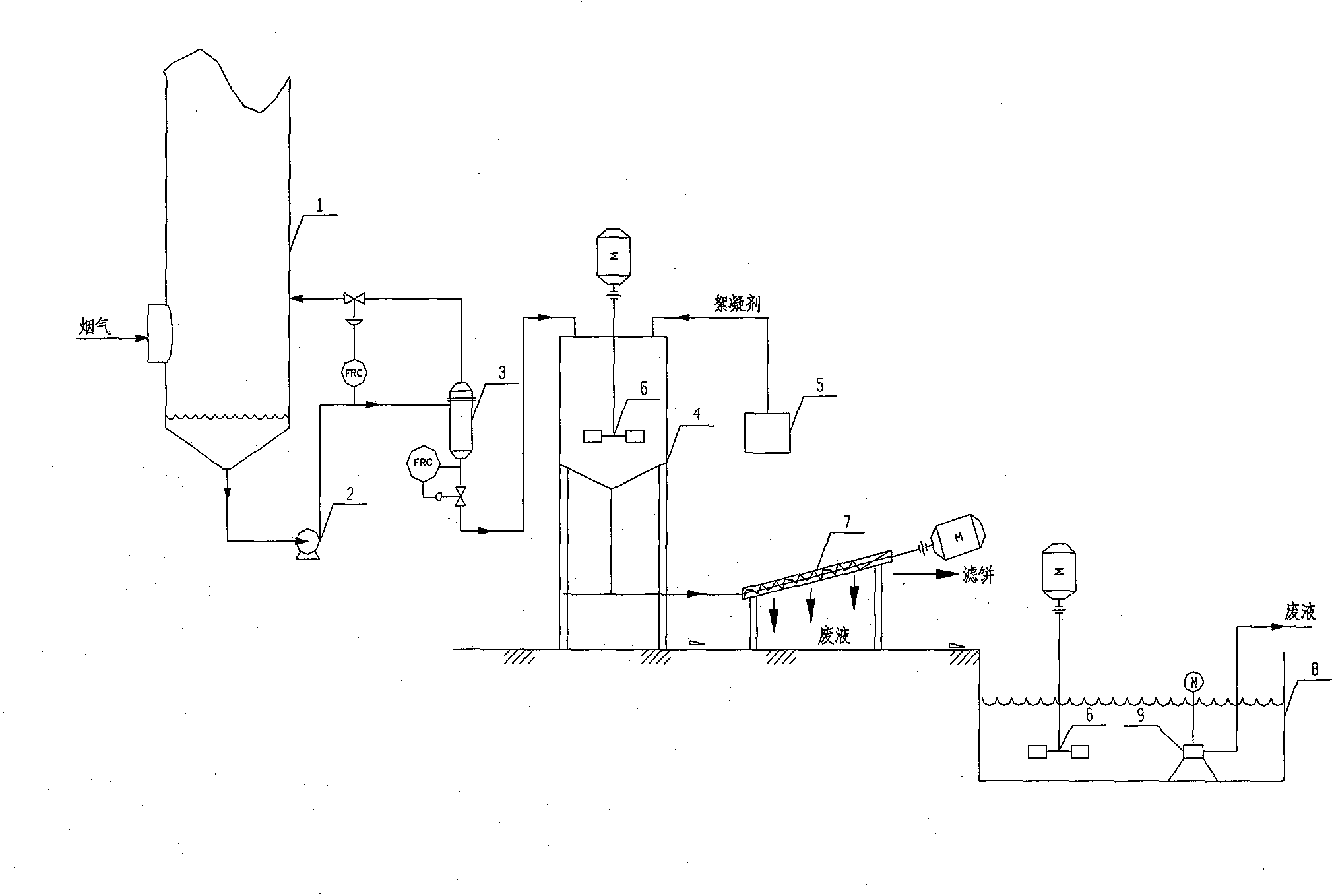
[0021] Below in conjunction with accompanying drawing, the present invention will be further described, as figure 1 As shown, the FCC flue gas enters the quenching tower from the middle and lower part of the quenching tower 1 of the flue gas desulfurization part to be quenched and saturated to form an acidic waste liquid containing particulate matter, sulfate and sulfite. The waste liquid is discharged from the bottom of the tower, and most of it is passed through The circulation pump 2 circulates back to the quenching tower 1, and the remaining waste liquid containing spent catalyst particles is sent to the hydrocyclone 3 for concentrated solid-liquid separation to separate the catalyst dust from the waste liquid, and the content of catalyst particles produced by separation is low The waste liquid returns to the quenching tower 1 through the top of the hydrocyclone 3 for circulation, and the concentrated waste liquid rich in catalyst particles that is produced through the sepa...


PUM


Abstract

The invention discloses a separation process of a waste catalyst in flue gas desulfurization wastewater. The method comprises the following steps: (1) waste liquid from a flue gas desulfurization part and comprising waste catalyst particles is concentrated in a hydro-cyclone separator; concentrated waste liquid rich in catalyst particles is delivered into a flocculating agent addition tank; (2) a flocculating agent is added into the waste liquid added into the flocculating agent addition tank from the step (1) and rich in catalyst particles under stirring; the waste liquid and the flocculating agent are well mixed; the mixed waste liquid is delivered into a dehydrator; and (3) in the dehydrator, the waste liquid is concentrated and dehydrated; dehydrated filter cake is directly transported, and the obtained filtrate is delivered into a sewage field for further treatments such as aeration. With the method, waste liquid discharge amount can be greatly reduced, equipment land occupation can be reduced, equipment investment can be saved, and waste catalyst transportation amount can be reduced.

Description

technical field [0001] The invention relates to a treatment method for waste catalysts in waste water, in particular to a treatment process for separating waste catalysts in catalytic cracking flue gas desulfurization waste water. Background technique [0002] At present, wet flue gas desulfurization process is generally adopted for catalytic cracking flue gas, and wet flue gas desulfurization process includes two types: one-time absorption process and renewable absorption process. No matter what process is used, when the flue gas is quenched, the catalyst particles entrained in the flue gas will be brought into the water; during the normal operation of the system, the content of spent catalyst in the water needs to be controlled to protect the pump, nozzle and pipeline Wait. The usual method is to adjust the waste catalyst content in the water by adjusting the amount of external drainage. Since the discharged wastewater contains spent catalysts, it is necessary to separat...

Claims


Application Information

Patent Timeline
IPC IPC(8): C02F9/04
Inventor 胡敏王刻文朱雷鸣王占顶
Owner LUOYANG PETROCHEMICAL ENG CORP SINOPEC
Learn More