Great-core-diameter optical fiber coupler and manufacturing method of great-core-diameter optical fiber coupler

An optical fiber coupler and a manufacturing method technology, which are applied to the coupling of optical waveguides, light guides, optics, etc., can solve the problems that the coupler cannot meet the needs of high-energy laser transmission, the fiber laser energy is uneven, and the fiber is not coaxially costed. Achieve the effect of reducing the difficulty of fiber coupling, reducing the risk of twisting, and reducing the non-axis of the fiber

Active Publication Date: 2015-02-11
NANJING CHUNHUI SCI & TECH IND
View PDF8 Cites 3 Cited by
  • Summary
  • Abstract
  • Description
  • Claims
  • Application Information

AI Technical Summary

Problems solved by technology

[0007] The technical problem to be solved by the present invention is that the fiber core diameter that the traditional multimode fiber coupler adopts is 50um or 62.5um, the coupler that this kind of fiber makes can't meet the transmission requirement of high-energy laser, and the coupling efficiency is low; The existing manufacturing methods of core-diameter fiber couplers have the accumulation of molten optical fibers in the coupling area, uneven laser energy output from the optical fibers, misalignment of optical fibers, or high cost.

Method used


Image

  • Great-core-diameter optical fiber coupler and manufacturing method of great-core-diameter optical fiber coupler
  • Great-core-diameter optical fiber coupler and manufacturing method of great-core-diameter optical fiber coupler
  • Great-core-diameter optical fiber coupler and manufacturing method of great-core-diameter optical fiber coupler

Examples


Embodiment 1

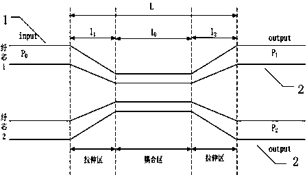
[0026] like figure 1 As shown, the large-core optical fiber coupler of this embodiment includes an input optical fiber 1 and two output optical fibers 2; the core diameter of the optical fiber is in the range of 200-600um, and the input optical fiber 1 and the output optical fiber 2 can have different core diameters. For optical fiber, the fiber core-skin ratio is 1:1.04 or 1:1.25.

[0027] Combined with the geometric structure of large core diameter fiber which is different from that of communication fiber, a theoretical model of large core diameter fiber coupling is established.

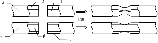
[0028] like figure 2 As shown, usually when the single-mode fiber 3 is coupled, since the core diameter 4 of the fiber is relatively thin (about 9-10um), the core diameter will become thinner and thinner during melting and stretching, and the light propagating in the core will gradually leak into the In the cladding layer 5, an optical fiber transmission medium layer composed of the cladding lay...

Embodiment 2

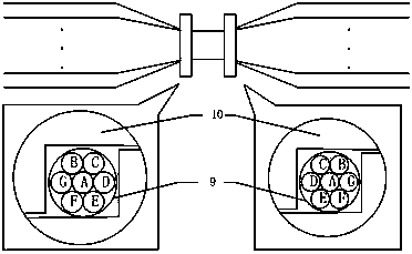
[0032] like image 3 As shown, the two ends of the coupling area are clamped by the fixture with a regular hexagonal cavity. The interior of the structure at both ends is related to the arrangement of seven optical fibers, in which the input optical fiber is in the center, and the six coupling optical fibers are around. The regular hexagons are closely arranged, and the relative positions are in one-to-one correspondence. Bind the arranged optical fibers with thin ropes 6, and then design a way to fix the arrangement of optical fibers by extruding and gluing two pieces of processing parts 7 according to the outer diameter of the seven optical fibers. The processing parts 7 need to be cut by wire To ensure the smoothness of the inner wall, so as not to damage the optical fiber. This kind of stable fiber arrangement with solidified workpieces at both ends of the coupling area can effectively ensure the uniformity of the splitting ratio after the fiber is melted. At the same tim...

Embodiment 3

[0034] like Figure 4 Shown, the microstructure processing of the coupler output end, the external structure includes a metal tube 11 for fixing, but the internal structure is different from the prior art, the difference lies in its ball lens 12 and large core diameter optical fiber 6, the front surface 12a of the lens and the rear surface 12b are spherical, the inner diameter of the front section 11a of the metal tube closely matches the outer diameter of the optical fiber used, the inner diameter of the rear section 11b of the metal tube closely matches the diameter of the ball lens, and the precision of the inner diameter of the metal tube ensures a large The coaxiality between the core fiber and the ball lens. The diameter of the ball lens should be larger than the core diameter of the coupling fiber, and the numerical aperture of the lens is NA1 smaller than the numerical aperture of the output fiber is NA2. Curing is carried out on the clean operating table in the purif...


PUM


Abstract

The invention discloses a great-core-diameter optical fiber coupler, which comprises an input optical fiber and n output optical fibers, wherein the n is greater than or equal to 1 but smaller than or equal to 6, the core diameter of the input optical fiber is 200 to 600mum, the core-to-sheath ratio range of the input optical fiber is 1:1.04 to 1:1.25, the core diameter of each output optical fiber is 200 to 400mum, the core-to-sheath ratio of the output optical fiber is identical to that of the input optical fiber, the input optical fiber and the output optical fibers are fixed and twisted in a coupling region, one end, in the coupling region, of the input optical fiber is the output end of the input optical fiber, the other end of the input optical fiber is the input end of the input optical fiber, one end, in the coupling region, of each output optical fiber is the input end of each output optical fiber, and the other end of each output optical fiber is the output end of the output optical fiber. The great-core-diameter optical fiber coupler has the advantages that the optical fiber coupling difficulty is low, the light splitting ratio of the coupler is uniform, the optical fiber uncoaxiality caused by optical fiber accumulation in the coupling region is reduced, the light spot divergence angle is smaller than 30 degrees, the transmittance is greater than 70 percent, any light splitting ratio can be realized, and the light splitting ratio deviation is +/-7 percent.

Description

technical field [0001] The invention relates to a large-core-diameter optical fiber coupler manufactured by a fusion tapering method and a manufacturing method thereof. Background technique [0002] There are three commonly used methods to achieve fiber coupling: erosion method, grinding method, and fusion tapering method. The erosion method is a chemical process treatment method, which is relatively simple, but the manufactured beam splitter has high requirements on the ambient temperature, and the stranding of the optical fiber affects its service life, so its practical value is low. The grinding method is a relatively traditional manufacturing method, which belongs to the category of optical cold processing. This method is cumbersome, the grinding and polishing process is difficult, and the volume of the beam splitter is relatively large. At present, this method is no longer used to make splitters. harness. The advantages of the fusion tapering process are: good directi...

Claims


Application Information

Patent Timeline
Patent Type & Authority Applications(China)
IPC IPC(8): G02B6/255
CPCG02B6/2552
Inventor 李辉王蓉李刚殷志东陈莉曾新华朱源圆冯陈
Owner NANJING CHUNHUI SCI & TECH IND
Why Eureka
Try Eureka