
Plasma etching method

A plasma and etching chamber technology, which is applied in semiconductor/solid-state device manufacturing, electrical components, circuits, etc., can solve problems such as difficult gasification and affecting the quality of plasma treatment, and achieve the elimination of residues, reduction of yttrium-containing particles and Formation of residue, effect of extending service life

Active Publication Date: 2015-02-11
ADVANCED MICRO FAB EQUIP INC CHINA
View PDF9 Cites 9 Cited by
  • Summary
  • Abstract
  • Description
  • Claims
  • Application Information

AI Technical Summary

Problems solved by technology

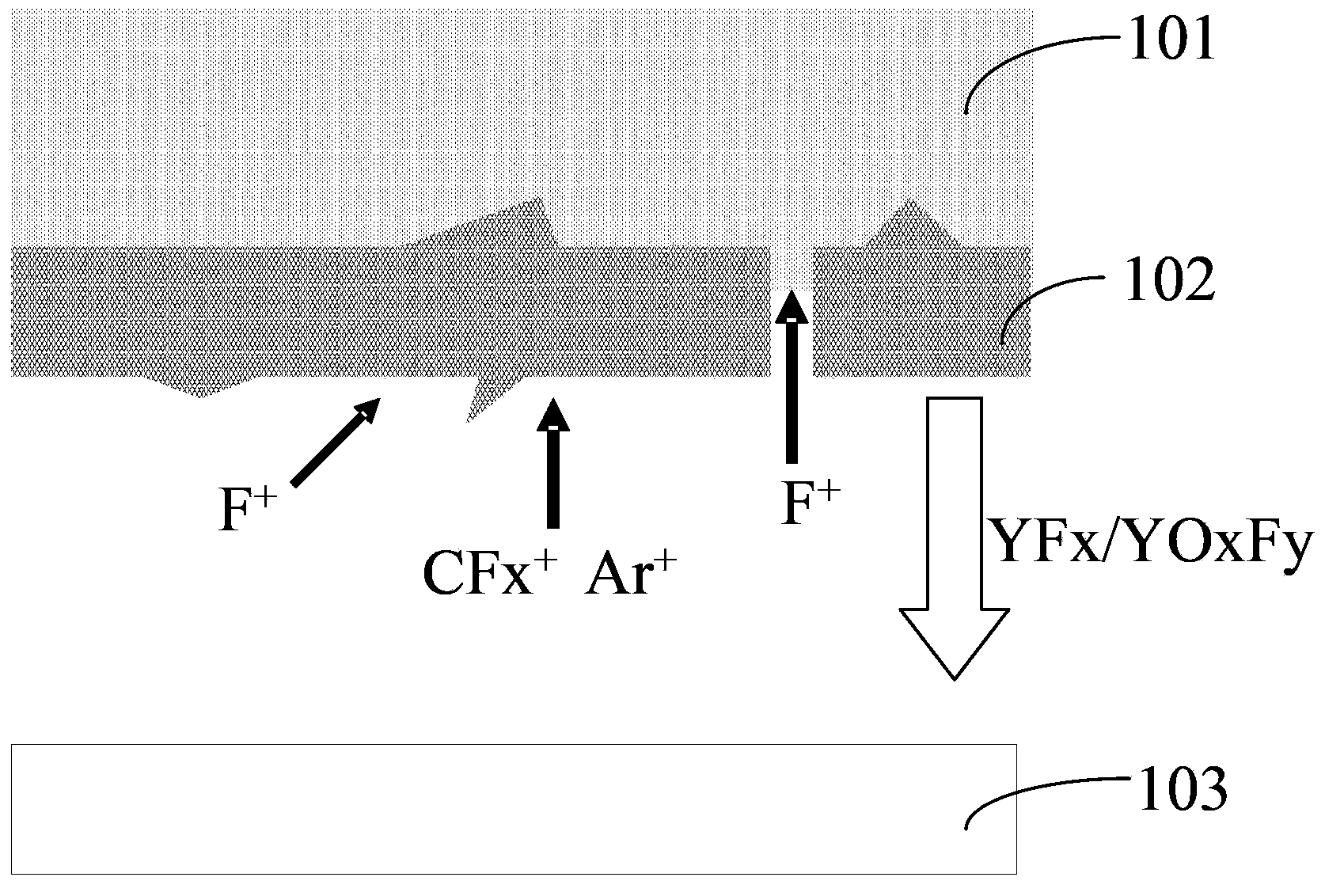
[0006] However, if figure 1 As shown, it is due to Y 2 o 3 Layer 101 reacts with fluorine-containing plasma to produce YF 3 102 is difficult to vaporize, and it is affected by Ar during plasma treatment + 、CFx + , F + and many other ion bombardment, the YF sputtered out x 、YO x f y Compounds containing Y will be re-deposited to the surface of the etched wafer 103 to form impurities or residues, which will accumulate on the surface of the photoresist and form residues on the surface of the dielectric material after deglue, affecting the quality of plasma treatment

Method used


Image

  • Plasma etching method
  • Plasma etching method
  • Plasma etching method

Examples


Embodiment Construction

[0022] In order to make the objectives, technical solutions and advantages of the present invention clearer, the embodiments of the present invention will be further described in detail below in conjunction with the accompanying drawings.

[0023] Those skilled in the art can easily understand other advantages and effects of the present invention from the contents disclosed in this specification. The present invention can also be implemented or applied through other different specific embodiments, and various details in this specification can also be modified or changed based on different viewpoints and applications without departing from the spirit of the present invention.

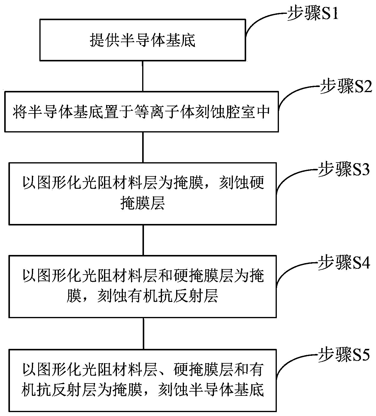
[0024] figure 2 It is a flow chart of the steps of the plasma etching method provided in the first embodiment of the present invention.

[0025] Such as figure 2 As shown, the plasma etching method provided by this embodiment includes the following steps:

[0026] Step S1: providing a semiconductor substrate 3...


PUM


Abstract

The invention relates to the technical field of a semiconductor, and discloses a plasma etching method. On the basis of a conventional fluorocarbon gas, Ar and O2, an N-containing gas is added to serve as an etching gas so as to react with carbon ions in plasma to generate a CN polymer depositing at the inner wall of a plasma etching cavity and the surface of a spray head, such that it is ensured that a yttrium oxide surface and yttrium fluoride generated through reaction are prevented from physical bombardment effect of the plasma, YFx sputtering is reduced, generation of yttrium-containing particles and residues are reduced, the residues brought when yttrium oxide covering the surface of the spray head is disposed at the surface of a semiconductor substrate to be etched during a plasma etching process is further decreased or even eliminated, and the surface quality of plasma etching is improved. Besides, the plasma etching method provided by the invention can also reduce damage caused by physical bombardment on the yttrium oxide covering the surface of the spray head during the plasma etching process and prolongs the service life of the spray head.

Description

Technical field [0001] The present invention relates to the field of semiconductor technology, and in particular to plasma etching technology using a shower head coated with yttrium oxide. Background technique [0002] At present, in the semiconductor manufacturing field, shower heads that supply air in a spray pattern to semiconductor wafers and other substrates are mostly used. Especially in plasma etching processing equipment, a carrier base for placing the substrate is provided in the processing chamber. , And a shower head is arranged at a position opposite to the carrier base, and a plurality of gas ejection holes are arranged on the surface of the shower head, and the gas is supplied in a spray shape to generate plasma. In the plasma processing device, the temperature of the chamber environment where the shower head is located is generally higher due to the need to generate plasma in the processing chamber. [0003] The base body of the traditional shower head is generally ...

Claims


Application Information

Patent Timeline
IPC IPC(8): H01L21/3065
CPCH01L21/3065
Inventor 王兆祥孙超
Owner ADVANCED MICRO FAB EQUIP INC CHINA
Learn More