Y-shaped power divider manufacturing technology

A manufacturing process and power divider technology, which is applied in the field of Y-type power divider manufacturing process, can solve the problems of reduced anti-corrosion performance of the power divider, difficult to guarantee the dimensional accuracy of the cavity, and large influence of telecommunication parameters, and achieves improved dimensional accuracy and Product quality, ensuring dimensional consistency and accuracy, and ensuring the effect of cavity dimensional accuracy

Inactive Publication Date: 2015-02-11
CHENGDU JINJIANG ELECTRONICS SYST ENG
View PDF6 Cites 9 Cited by
  • Summary
  • Abstract
  • Description
  • Claims
  • Application Information

AI Technical Summary

Problems solved by technology

[0012]The traditional manual flame brazing method has the following problems and defects: 1. Many processing procedures and long production cycle; High; 3. Traditional manual flame brazing is local heating, the temperature uniformity is poor during welding, the deformation of the cavity after welding is large, and the dimension accuracy of the cavity is difficult to guarantee; 4. The Y-shaped power divider formed by traditional manual flame brazing Poor consistency, poor dimensional accuracy, great impact on telecommunications parameters, increasing the difficulty of debugging; 5. In order to make the brazing filler metal wet and capillary flow in the base metal gap, flux must be used when brazing and filling the gap, while The brazing flux has a strong corrosion effect on the base metal itself, and the residual flux residue cannot be completely removed after brazing, resulting in a significant reduction in the anti-corrosion performance of the power divider and a greatly shortened service life
Therefore, traditional manufacturing methods are difficult to meet the quality requirements of products and the needs of mass production

Method used


Image

  • Y-shaped power divider manufacturing technology
  • Y-shaped power divider manufacturing technology
  • Y-shaped power divider manufacturing technology

Examples


Embodiment Construction

[0052] The technical solution of the present invention will be further described in detail below in conjunction with the accompanying drawings, but the protection scope of the present invention is not limited to the following description.

[0053] A manufacturing process for a Y-shaped power divider, including a processing step for an upper cover plate, a processing step for a lower cavity, and a vacuum brazing forming step:

[0054] The described upper cover plate processing step comprises the following sub-steps:

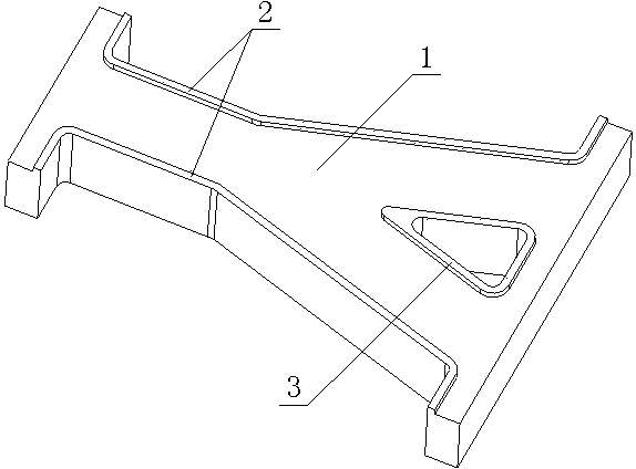
[0055] S11: Material preparation: Cut the raw materials into the shape of the upper cover according to the product design size, such as figure 1 As shown, including the upper cover body 1, the edge boss 2 and the Y branch groove convex stop 3, reserve 3~5mm machining allowance and 3~5mm thickness allowance;

[0056] S12: CNC rough milling: Use CNC milling machine to complete the rough milling of the upper cover, leaving a margin of 2~3mm on one side;

[0057] S1...


PUM


Abstract

The invention discloses a Y-shaped power divider manufacturing technology which comprises upper cover plate processing, lower cavity processing and vacuum brazing molding and specifically comprises the steps of S31: mounting an upper cover plate and a lower cavity in trial, and guaranteeing that an edge boss (2) and an edge groove (5) as well as a Y-branch slot convex bayonet (3) and a Y-branch slot concave bayonet (6) are tightly attached; S32: performing pickling to remove impurities; S33: assembling the upper cover plate, the lower cavity and a brazing material; S34: performing vacuum brazing; S35: performing numerical control processing on the appearance of a power divider and a flange disk; S36: drilling and hinging pin holes; S37: performing electrochemical treatment; S38: testing telecommunications parameters. According to the Y-shaped power divider manufacturing technology, the welding deformation caused by multi-time manual flame welding is avoided; the upper cover plate and the lower cavity are positioned by the boss, the groove and the bayonets, so that the size consistency and the precision of the power divider are guaranteed; when the parts such as the boss, the groove and the bayonets are designed, the embedding thickness of a welding sheet is considered; furthermore, a fit clearance is increased to 0.02-0.04mm, so that the flowability of brazing material joint filling is guaranteed during welding, and the cavity size precision of the assembled power divider is guaranteed.

Description

technical field [0001] The invention relates to the field of microwave device processing, in particular to a manufacturing process of a Y-shaped power divider. Background technique [0002] Y-branch waveguides are commonly used devices in integrated optics, and are widely used in waveguide devices such as beam splitters, optical switches and modulators. The current microwave device manufacturer manufactures the Y-shaped power divider as follows: Divide the Y-shaped power divider into multiple parts, and use the traditional manual flame brazing method to assemble and weld the shape several times, including the cover plate, the Y branch groove and two Combined welding of flanges. [0003] Its specific technological process is as follows: [0004] 1. Parts processing: [0005] 1.1: Cover plate processing: material preparation → counting milling → wire cutting → pliers. [0006] 1.2: Y branch groove processing: material preparation→digital milling→heat treatment annealing→di...

Claims


Application Information

Patent Timeline
Patent Type & Authority Applications(China)
IPC IPC(8): H01P11/00H01P5/12
Inventor 周衢龚建君涂学明
Owner CHENGDU JINJIANG ELECTRONICS SYST ENG
Why Eureka
Try Eureka