

Photocurable resin composition for imprinting, method for producing same, and structure
A curable resin and composition technology, applied in semiconductor/solid-state device manufacturing, microstructure technology, microstructure devices, etc., can solve problems such as inability to correctly reflect the structure, and achieve curing shrinkage inhibition, high surface hardness, and inhibition of yellowing. changing effect
Inactive Publication Date: 2015-02-11
SOKEN CHEM & ENG CO LTD
View PDF13 Cites 0 Cited by
- Summary
- Abstract
- Description
- Claims
- Application Information
AI Technical Summary
Problems solved by technology
[0004] In the above-mentioned photoimprinting, there is a problem that the resin shrinks during curing, and a structure that does not accurately reflect the shape of the original mold is produced.
Method used
View moreImage
Smart ImageViewing Examples

Examples
Embodiment 1~4
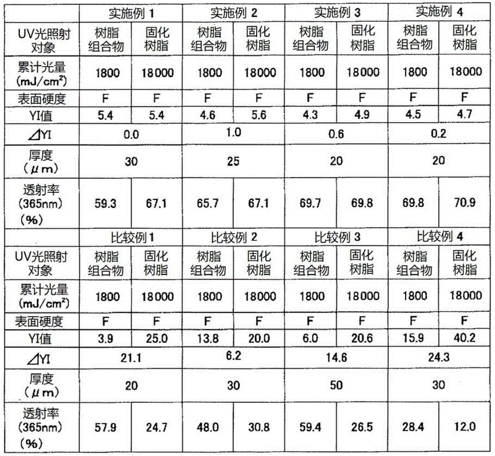
[0134] In 75 parts by weight tripropylene glycol diacrylate (TPGDA), 20 parts by weight methyl methacrylate (MMA), 5 parts by weight glycidyl methacrylate (GMA), as photoinitiator, with the 1-Hydroxy-cyclohexyl-phenyl-ketone ("IRGACURE184" manufactured by BASF Corporation) and bis(2,4,6-trimethylbenzoyl)-phenylphosphine oxide ("IRGACURE819" manufactured by BASF Corporation) , to prepare a photocurable resin composition. Its composition is shown in Table 1.
Login to View More PUM
| Property | Measurement | Unit |
|---|---|---|
| hardness | aaaaa | aaaaa |
| shrinkage | aaaaa | aaaaa |
Abstract
[Problem] To provide a photocurable resin composition in which curing shrinkage during optical imprinting is suppressed. Also to provide a photocurable resin composition capable of producing, by optical imprinting, a structure which has a high surface hardness and in which occurrence of yellowing is suppressed even when subjected to irradiation with ultraviolet radiation and the like. [Solution] This photocurable resin composition for imprinting contains a (meth)acrylic monomer (A) and a photoinitiator (B), and is characterized in that the photoinitiator (B) comprises a combination of an alkylphenone-based photoinitiator (B1) and an acylphosphine oxide-based photoinitiator (B2), and the blending ratio of the alkylphenone-based photoinitiator (B1) and the acylphosphine oxide-based photoinitiator (B2) (B1:B2) is between 1:99 and 90:10 by weight.
Description
technical field [0001] The present invention relates to a photocurable resin composition for imprint, a method for producing a structure using the photocurable resin composition, and a structure formed using the photocurable resin composition. Background technique [0002] Imprint technology refers to the technology of pressing the master mold with nano- or micron-scale fine structure formed on the surface to the liquid resin, and transferring the fine structure of the mold to the resin. A structure with a microstructure formed by transfer is used as an imprint mold, an anti-reflection film, a diffusion film, etc., depending on the shape of the microstructure, and is used in semiconductor materials, optical materials, storage media, micro-motors, organisms, environments, etc. various fields. [0003] As the imprinting method, thermal embossing and photoimprinting etc. are mentioned. In the said thermal embossing, a mold having a predetermined shape formed on its surface is ...
Claims
Login to View More Application Information
Patent Timeline
 Patent Type & AuthorityApplications(China)
IPC IPC(8): H01L21/027B81C99/00C08F2/50
CPCC08F2/50G03F7/0002Y10T428/24612B29C59/005B29C59/026C08F4/28C08F22/10C08J5/00H01L21/027
Inventor山田纮子须藤康夫宫泽幸大
OwnerSOKEN CHEM & ENG CO LTD