A hazardous waste incineration feeding device

A hazardous waste and feeding device technology, applied in the direction of incinerators, combustion methods, combustion types, etc., can solve problems such as economic losses, increased operating costs, loose and uneven states, etc., achieve stable and uniform feeding, and save manpower , the effect of controlling the combustion temperature

Active Publication Date: 2017-01-04
BMEI
View PDF9 Cites 0 Cited by
  • Summary
  • Abstract
  • Description
  • Claims
  • Application Information

AI Technical Summary

Problems solved by technology

[0004] As far as the reliability of the system is concerned, the three components of the pusher head, the first-level door and the second-level door need four (2 forward and 2 backward) limit switches, which will obviously lead to a high failure rate of the equipment in use; In addition, the water jacket has the disadvantage of being easy to corrode. When the circulating water system fails, if the emergency circulating water system is not activated in time, it is very easy to cause vaporization in the water jacket, resulting in an increase in the pressure in the water jacket, which may cause weld seam failure. Therefore, due to reliability factors, when the water jacket fails, the furnace will be shut down for maintenance, but this will obviously affect the operating efficiency of the incineration system and bring a certain degree of economic loss;
[0005] As far as the functionality of the system is concerned, since the limit switch is installed in a welding manner that cannot move freely, the push head can only be pushed to the full stroke each time, and the state of the material entering the hopper is loose and uneven, resulting in a single feed The amount is difficult to control, and due to the limited length of the push head, in order to prevent the upper material from falling into the back of the push head when the push head is moving forward, the hopper is not allowed to store materials, thus limiting the single grab material amount of the driving grab and increasing the grab The number of operations, the utilization efficiency of equipment is reduced, and the operating cost is increased accordingly.

Method used


Image

  • A hazardous waste incineration feeding device
  • A hazardous waste incineration feeding device
  • A hazardous waste incineration feeding device

Examples


Embodiment Construction

[0029] The technical solutions of the present invention will be further described in detail below in conjunction with the accompanying drawings and embodiments.

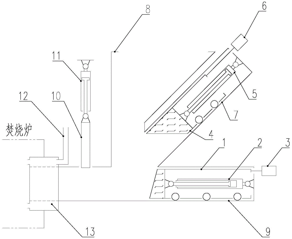
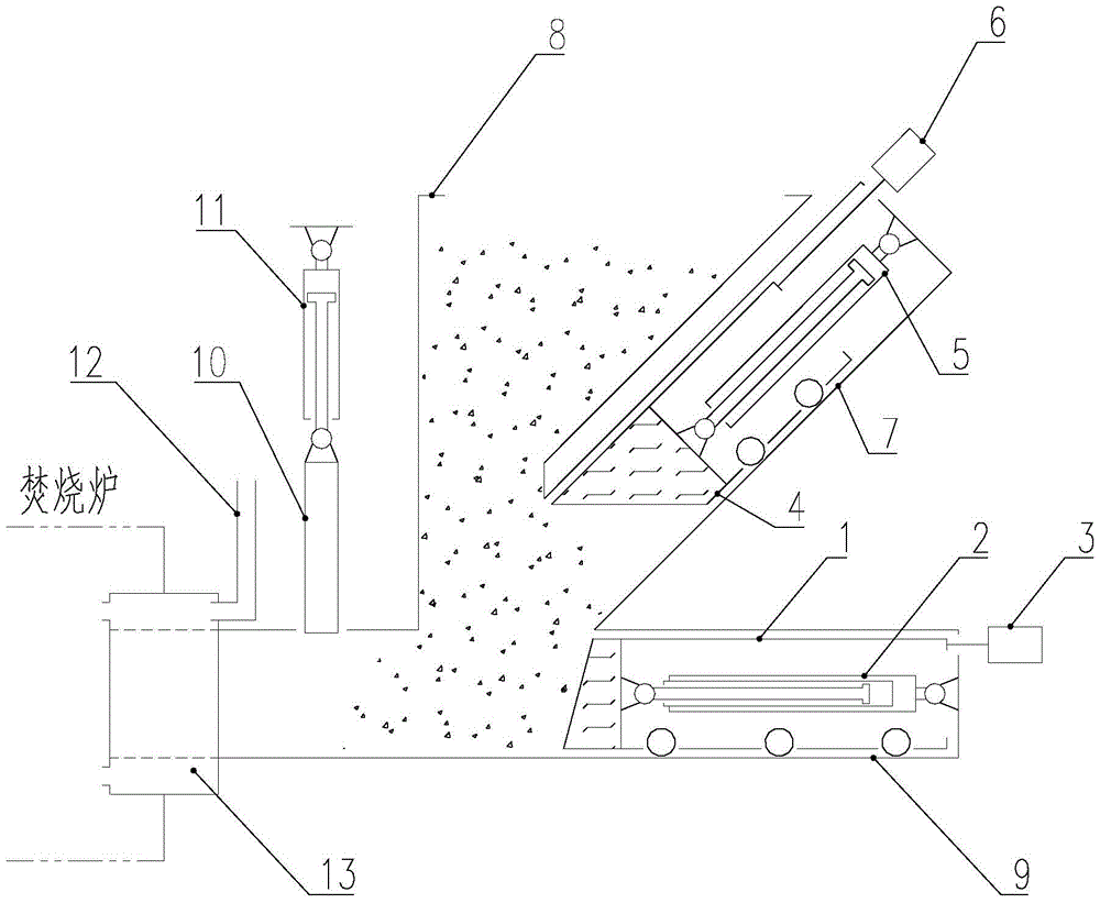
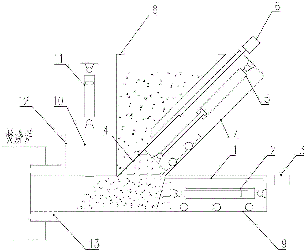
[0030] Such as figure 1 A hazardous waste incineration feeding device shown includes a substrate, a pushing unit, a pressing unit and an air-cooling unit. The substrate includes a pushing channel 9, a hopper 8 and a pressing channel 7, and the pushing channel 9 runs along the substrate. The bottom is set in the horizontal direction, the hopper 8 is set on the top of the substrate, and the pressing channel 7 is arranged obliquely between the pushing channel 9 and the hopper 8; the pushing unit is placed on the pushing channel 9 of the hopper 8, and along the pushing Road 9 moves, and the pressing unit is placed in the pressing channel 7 of the hopper 8, and moves along the pressing channel 7; The cooling air passage 12 on the cooling jacket 13, the air-cooling jacket 13 is ring-sleeved at the connection between the p...


PUM


Abstract

The invention provides an incineration feeding device for hazardous wastes. The device comprises a base body, a material pushing unit, a material pressing unit, an air cooling unit and a control part, wherein the base body comprises a material pushing way, a material hopper and a material pressing way; the material pressing way is arranged along the horizontal direction of the bottom part of the base body; the material hopper is arranged on the top part of the base body; the material pressing way is obliquely arranged between the material pushing way and the material hopper; the material pushing unit is arranged in the material pushing way; the material pressing unit is arranged in the material pressing way; the tail end of the material pushing way is connected to an incineration furnace; the air cooling unit is arranged at the connection of the material pushing way and the incineration furnace; the control part communicates with the material pushing unit and the material pressing unit respectively. According to the device, as a pull-wire type displacement sensor transmits the stroke values of a material pushing head and a material pressing head in real time, the automatic or semi-automatic feeding after single massive feeding is realized; the utilization rate of feeding equipment is improved; the labour is saved.

Description

technical field [0001] The invention relates to the technical field of hazardous waste treatment for environmental protection, in particular to an incineration feeding device for hazardous waste. Background technique [0002] At present, the feeding device of the incineration system used to treat hazardous waste mainly includes a water jacket, a hopper, a pushing channel, a hydraulic system, a primary door, a secondary door, a pushing head and a limit switch. The feeding process is usually It is: firstly, the first level door is opened, and the material falls from the hopper to the front of the pushing head; then the first level door is closed, and the second level door is opened, and the hydraulic system drives the pushing head forward, until the limit switch at the end of the material path is triggered, and the progress is stopped. At this time, all the materials loaded in a single batch are pushed into the incinerator; then the pushing head returns to the initial position...

Claims


Application Information

Patent Timeline
Patent Type & Authority Patents(China)
IPC IPC(8): F23G7/00F23K3/00
CPCF23G7/00F23G2205/10F23K3/00
Inventor 徐家麒张毅杨红芬汪洪伟于炜朱宇坤王德昊孙延波司千刘春慧李晓岩杨帆
Owner BMEI
Why Eureka
Try Eureka