

Novel flywheel energy storage device
A technology of flywheel energy storage and flywheel, which is applied in the direction of electromechanical devices, holding devices with magnetic attraction or thrust, and control of mechanical energy, can solve the problems of unreachable and low investment scale, and achieve high speed, increase energy storage capacity, and structure simple solid effect
- Summary
- Abstract
- Description
- Claims
- Application Information
AI Technical Summary
Problems solved by technology
Method used
Image

Examples
Embodiment Construction
[0028] The specific implementation manner of the present invention will be further described below in conjunction with the accompanying drawings.
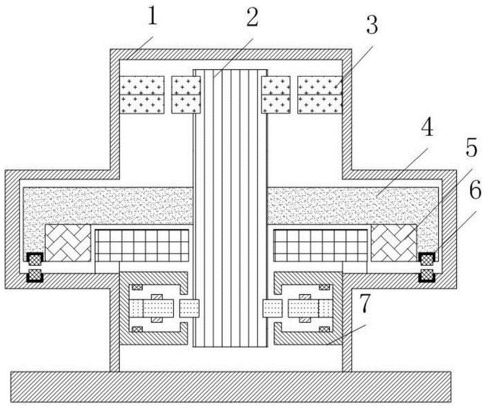
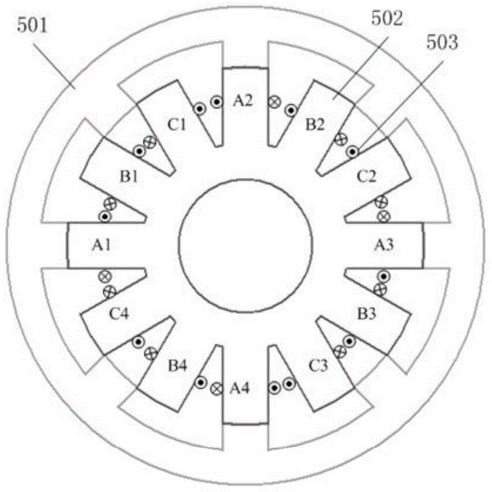
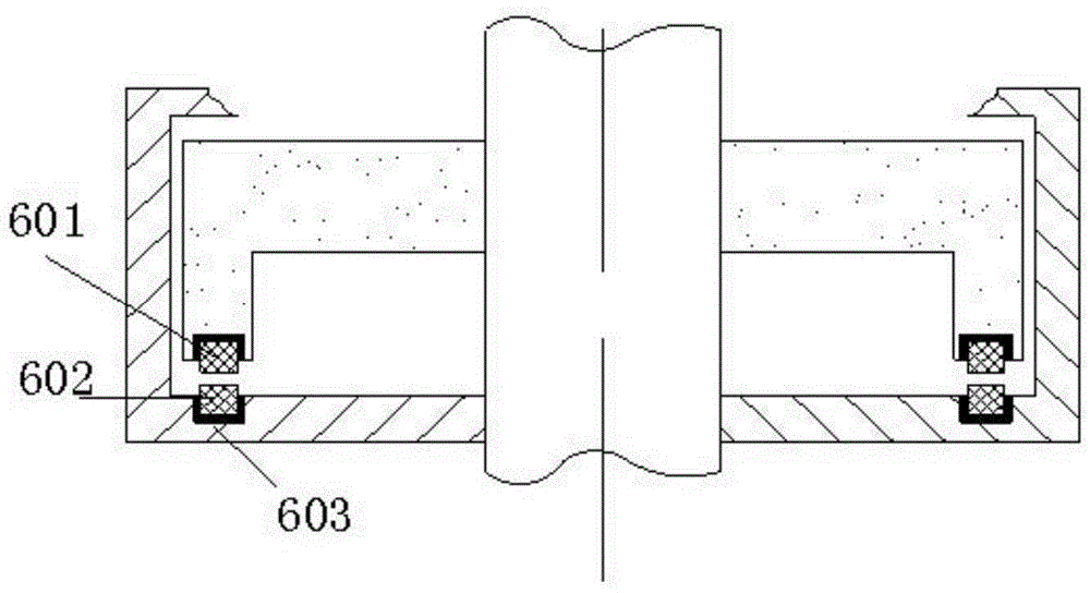
[0029] Such as figure 1As shown, the present invention includes a vacuum container 1, a rotating shaft 2, a permanent magnet radial bearing 3, a flywheel 4, a single-winding outer rotor magnetic levitation switched reluctance motor 5, a permanent magnet unloading bearing 6, a permanent magnet bias radial-axial magnetic Bearing 7. The permanent magnetic radial bearing 3 is nested on the upper end of the rotating shaft 2, and acts as a backup bearing. The lower end of the rotating shaft is sequentially fitted with a flywheel 4, a single-winding outer rotor magnetic levitation switched reluctance motor 5, a permanent magnet bias radial-axial magnetic bearing 7, and the flywheel 4 is fixedly connected to the outer rotor of the single winding outer rotor magnetic levitation switched reluctance motor. The permanent magnet unloading sha...
PUM
 Abstract
Description
Claims
Application Information