Main and auxiliary motor coupling and range-extending driving system

A drive system and main drive technology, applied in engine-driven traction, motors, electric vehicles, etc., can solve the cost, weight, space, structure, efficiency difficulties, difficult to meet the requirements of multiple working conditions and high power of vehicles, Problems such as noise, vibration efficiency, and difficult control, to achieve the effect of convenient integration and layout, reducing the chance of high current impact, and reducing the diameter of the motor

Inactive Publication Date: 2015-03-18
CHANGZHOU HAOKANG NEW ENERGY DEV
View PDF5 Cites 1 Cited by
  • Summary
  • Abstract
  • Description
  • Claims
  • Application Information

AI Technical Summary

Problems solved by technology

However, if an independent single-cylinder generator set is added, its low power will make the generator and the drive motor often work at the same time, which is difficult to meet the requirements of multiple working conditions and high power of the vehicle, and there are difficulties in noise, vibration, efficiency, control, etc. The safety and reliability are low, which is not conducive to the driving and riding comfort of the car; the addition of independent generator sets with high power will bring difficulties to cost, weight, space, structure, efficiency, etc.
Analysis of the technical route of extended-range electric vehicles at home and abroad is to increase the independent power generation system, which is not well integrated with the overall optimization control of the vehicle, and it is difficult to ensure the overall efficiency of the vehicle, which limits the development of integrated and intelligent electric vehicles with extended range

Method used


Image

  • Main and auxiliary motor coupling and range-extending driving system
  • Main and auxiliary motor coupling and range-extending driving system
  • Main and auxiliary motor coupling and range-extending driving system

Examples


Embodiment Construction

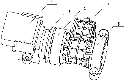
[0016] figure 1 Shown is a perspective view of the present invention with the coupling of primary and secondary motors taking into account the range-extending drive system. In the figure 1 is the engine, in the figure 2 is the clutch, in the figure 3 is the auxiliary motor, in the figure 4 is the reducer, and in the figure 5 is the main motor. motor.

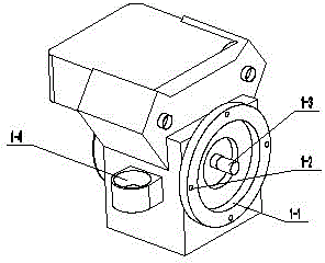
[0017] figure 2 Shown is the stereogram of engine among the present invention, among the figure 1-1 is the spigot that is connected with clutch, among the figure 1-2 is the threaded hole that is connected with clutch, among the figure 1-3 is output spline shaft, among the figure 1 -4 is the supporting hole of the engine, which bears the weight of the whole unit.

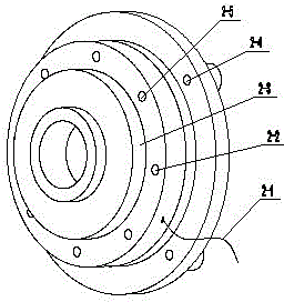
[0018] image 3 It is the perspective view of the clutch in the present invention, among the figure 2-1 is the low pressure control line of the clutch, among the figure 2-2 is the installation through hole of the clutch and the engine threaded hole 1-2, among the f...


PUM


Abstract

The invention discloses a main and auxiliary motor coupling and range-extending driving system, which adopts two motors, wherein one motor serves as a main driving motor, the other motor serves as a generator for a range extender and also is used for being coupled with the main driving motor to take part in the driving operation (hereafter called auxiliary motor), one end of the output shaft of the auxiliary motor is connected to an engine by a clutch while the other end of the output shaft of the auxiliary motor is placed opposite to the output shaft of the main driving motor, and coaxially inserted into the coupler of a reducer; when in driving, the engine is separated from the auxiliary motor by the clutch, and meanwhile combine with the coupler in the reducer, thus achieving the main and auxiliary motor coupling driving; when a vehicle has small requirement on the power, the auxiliary motor can be idle or compatible for generating electricity; the above components are integrated into a machine, a plurality of driving modes, including single motor independent driving when in small power, double motor coupling driving when in large power, engine and main and auxiliary motor combined driving when in extra large load and range-extending generation driving when a battery is lack of power can be obtained under the network control of the whole vehicle; the system includes the engine, the clutch, the auxiliary motor, the reducer, the main driving motor, a generation unit controller and a double-motor controller.

Description

technical field [0001] The invention belongs to the technical field of electric vehicles, and more specifically relates to a driving system with coupling of main and auxiliary motors and extended range. Background technique [0002] With the development of society, the problems of limited oil resources and environmental pollution have become increasingly prominent, which makes electric vehicles more and more attention from governments and all walks of life in the world. Among the types of electric vehicles, pure electric vehicles are characterized by their zero emissions, The advantages of high efficiency, convenient driving, comfortable operation, and extensive sources of electric energy have become the ultimate development direction of the future automobile industry. However, at present, the battery loaded in pure electric vehicles is large in size, heavy in weight, high in price, long in charging time, and short in continuous mileage, which have become the bottleneck of i...

Claims


Application Information

Patent Timeline
Patent Type & Authority Applications(China)
IPC IPC(8): B60L11/02B60L11/18B60L50/10
CPCY02T10/64Y02T10/7072
Inventor 马军张汉新刘冰王蕾刘朝祥
Owner CHANGZHOU HAOKANG NEW ENERGY DEV
Why Eureka
Try Eureka