Continuously-adjustable adjustment method and device for valve timing of engine

A technology of valve phasing and adjustment method, which is applied in the directions of engine components, machines/engines, valve devices, etc., can solve the problem of poor engine fuel economy harmful gas emission indicators, insignificant improvement effect of harmful gas emission indicators, and can not meet the requirements of simultaneous increase Or at the same time reduce problems such as improving intake and exhaust conditions, reducing useful power loss, and improving power performance

Inactive Publication Date: 2015-03-18
王自勤
View PDF4 Cites 6 Cited by
  • Summary
  • Abstract
  • Description
  • Claims
  • Application Information

AI Technical Summary

Problems solved by technology

At present, in the variable valve timing technology: one method is to use different cams to adjust the valve timing, this method can only obtain the best valve timing at a few specific speeds, there are Disadvantages such as inability to achieve continuous phase adjustment
Another method is to adjust the valve timing by changing the relative angle between the camshaft and the crankshaft. In this method, if the advance angle is increased, the lag angle will be reduced, and if the advance angle is reduced, the lag will inevitably be increased. Angle, can not meet the adjustment requirements of the valve advance angle and lag angle to increase or decrease simultaneously with the increase or decrease of the engine speed, etc.
Another type of method is to use hydraulically driven valves, and use solenoid valves or other hydraulic valves to control the hydraulic oil circuit that drives the valves to realize the adjustment of the gas distribution phase. This method requires more solenoid valves or other hydraulic valves, The structure and control are complicated, and the high-frequency response performance of the solenoid valve is not good, etc.
Due to the many defects of the above-mentioned variable valve timing technology, the improvement effect of the engine equipped with the variable valve timing system on the fuel economy and harmful gas emission indicators is not obvious
At present, most engines are not equipped with variable valve timing devices, and the fuel economy and harmful gas emission indicators of the engines are poor.

Method used


Image

  • Continuously-adjustable adjustment method and device for valve timing of engine

Examples


Embodiment 1

[0021] An adjustment method for continuously adjustable engine valve timing, comprising:

[0022] (1) A gas distribution phase adjuster is connected in parallel in the hydraulic oil circuit between the cam cylinder and the valve cylinder of the variable valve mechanism of the hydraulic variable cam follower;

[0023] (2) The gas distribution phase regulator includes the gas distribution phase regulator oil cylinder, the gas distribution phase regulator piston, the piston return device and the limit device, and the return force generated by the piston return device keeps the piston at zero position ( The position where the volume of the cylinder of the valve phase regulator is zero) moves in the direction, the stroke of the piston of the valve phase regulator from zero position to the limit device is controlled by the limit device, and the oil flowing into the cylinder of the valve phase regulator is controlled The liquid volume, and then control the moment when the oil flows i...

Embodiment 2

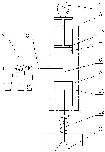
[0028] An adjustment device for continuously adjustable engine valve timing, including a cam 1 and a valve 2, a hydraulic system 3 is provided between the cam 1 and the valve 2, wherein: a hydraulic oil circuit 6 between the cam cylinder 4 and the valve cylinder 5 A gas distribution phase regulator 7 is connected in parallel in the middle, and the gas distribution phase regulator 7 includes a gas distribution phase regulator cylinder 8, a gas distribution phase regulator piston 9, a gas distribution phase regulator spring 10, and a gas distribution phase regulator limit rod 11 , The gas distribution regulator piston 9 is located in the gas distribution regulator cylinder 8, and the gas distribution regulator piston 9 rear end is provided with a gas distribution regulator spring 10 and a gas distribution regulator limit rod 11.

[0029] The hydraulic system overcomes the pretightening force of the valve phase regulator spring 10 and the force of the valve phase regulator spring ...


PUM


Abstract

A method for regulating continuously variable valve timing of an engine, comprising: a valve timing regulator is parallel-connected in a hydraulic fuel way (6) between a cam cylinder (4) and a valve cylinder (5) of a variable valve mechanism of a hydraulic variable cam follower; the valve timing regulator (7) comprises a valve timing regulator cylinder (8), a valve timing regulator piston (9), a piston resetting apparatus (10), and a limiting apparatus (11); by means of having the piston (9) always kept in a movement in the direction of a zero position by a resetting force generated by the piston resetting apparatus (10), and of having strokes made by the valve timing regulator piston (9) between the zero position and the limiting apparatus controlled by the limiting apparatus (11), the volume of a hydraulic fluid that flows into the valve timing regulator cylinder (8) is controlled, thus controlling timing for the hydraulic fluid to flow into the valve cylinder and an effective-work sustaining angle corresponding to rotation of a cam, and implementing continuous and variable valve timing control. Also provided is an apparatus for regulating continuously variable valve timing of an engine. The method and apparatus allow for increased fuel economy and for improved dynamics and emission reduction of an engine.

Description

technical field [0001] The invention relates to an engine, in particular to an adjusting method for continuously adjustable engine valve lift, and also relates to a device used in the adjusting method. Background technique [0002] The engine has different requirements on the valve timing at different speeds. Adjusting the valve timing according to the engine speed is one of the important technical means to improve engine combustion conditions, improve fuel economy and reduce harmful gas emissions. At present, in the variable valve timing technology: one method is to use different cams to adjust the valve timing, this method can only obtain the best valve timing at a few specific speeds, there are Can not realize the continuous adjustment of the phase and other shortcomings. Another method is to adjust the valve timing by changing the relative angle between the camshaft and the crankshaft. In this method, if the advance angle is increased, the lag angle will be reduced, and...

Claims


Application Information

Patent Timeline
Patent Type & Authority Applications(China)
IPC IPC(8): F01L1/34F01L9/11F01L9/14
CPCF01L9/02F01L1/3442F01L9/11F01L9/14
Inventor 王自勤谢庆生田丰果
Owner 王自勤
Why Eureka
Try Eureka