Microlens array based large-power ceiling lamp

A technology of LED ceiling lamp and microlens array, which is applied to the parts of lighting device, cooling/heating device of lighting device, lighting and heating equipment, etc. Efficiency, low utilization rate of LED light-emitting light energy, etc., to achieve the effect of being conducive to assembly line production, efficient and reliable performance, and simple structure

Inactive Publication Date: 2015-03-18
CHINA JILIANG UNIV
View PDF3 Cites 8 Cited by
  • Summary
  • Abstract
  • Description
  • Claims
  • Application Information

AI Technical Summary

Problems solved by technology

[0003] LED light extraction efficiency is low. At present, through optical design and LED chip technology, the internal quantum efficiency of LED reaches more than 90%, but the external quantum efficiency is only 30% to 50%. In addition to reasonable thermal management, optical design must also be optimized. And research; primary packaging optical design will affect the external quantum efficiency of LED devices, so that the overall light energy utilization rate of LED lamps is low, so the secondary optical design is particularly important
[0004] Secondly, as a solid-state light source, LEDs must form a certain array of multiple point sources to meet the total luminous flux requirements of lighting-level light sources when realizing power-level lighting. Light scattered over a range of angles or illuminated unevenly on a defined plane
Furthermore, although high-power LEDs can meet the brightness requirements of lighting, due to the high operating temperature, heat dissipation is required through a radiator, and the heat dissipation effect of the existing aluminum substrate is not ideal, resulting in a short service life of the LED chip
[0005] The existing LED chips are arranged in the center of the lamp in an array. This arrangement reduces the utilization rate of LED light energy. In order to achieve the corresponding required brightness, it is necessary to rely on increasing the number of LED chips, resulting in LED ceiling lamps working Higher temperature, higher power consumption, higher cost

Method used


Image

  • Microlens array based large-power ceiling lamp
  • Microlens array based large-power ceiling lamp
  • Microlens array based large-power ceiling lamp

Examples


Embodiment Construction

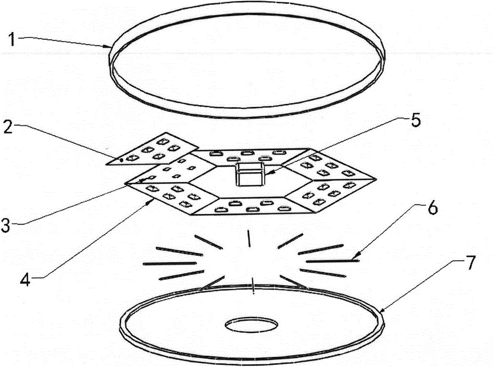
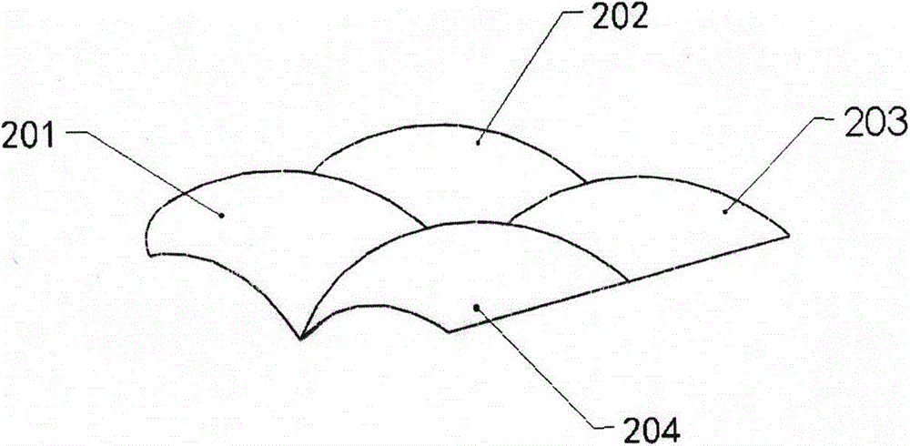
[0024] figure 1 Among them, a high-power LED ceiling lamp based on a microlens array includes a lamp housing, a light source module, a driving power supply 5, and a heat dissipation system; the lamp housing includes a chassis 7 and a lampshade 1; the light source module includes a microlens array 2. LED array light source 3 and substrate 4; the microlens array is composed of four-petal microlenses with the same number as the LED lamp beads; the heat dissipation system includes thermal conductive glue and ceramic heat sink 6; the lampshade 1 is located at The top of the lamp is tightly combined with the chassis through the fixing parts. The LED array light source 3 and the driving power supply 5 are both located on the substrate 4. The fixing parts are combined with the substrate 4. The driving power supply 5 is located at the center of the ring formed by the substrate 4. In the center; the LED array light source 3 is covered with a microlens array 2, and each four-petal microl...


PUM


Abstract

The invention discloses a microlens array based large-power ceiling lamp. The microlens array based large-power ceiling lamp comprises a housing, a light source module, a driving power supply and a radiating system; the housing comprises a base plate and a lampshade; the light source module comprises a microlens array, an LED array light source and a bottom plate; the radiating system comprises a heat transfer adhesive and a ceramic radiating sheet; the lampshade is positioned on the top of the lamp and is closely combined with the base plate through a clamp; the LED array light source and the driving power supply are both positioned on the bottom plate and are combined with the bottom plate through fixing parts; the driving power supply is positioned in the center of a ring belt which is composed of the bottom plate; the microlens array cover the LED array light source, and each microlens is corresponding to single LED lamp bead; the radiating system is positioned on the rear surface of the bottom plate; the ceramic radiating sheet is in filling connection with the bottom plate through the heat transfer adhesive, wherein the bottom plate is combined with the base plate through the fixing part. According to the microlens array based large-power ceiling lamp, the secondary optical design is performed, thus the light collecting efficiency is improved, the light diffusion angle is expanded, the radiating effect is obvious, and the appearance is nice.

Description

technical field [0001] The invention relates to an LED ceiling lamp, in particular to a high-power LED ceiling lamp based on a microlens array. Background technique [0002] In recent years, LED has been used as a new generation of lighting source because of its high brightness, small size, low power consumption, green, environmental protection and many other advantages. Existing LED ceiling lamps use multiple LED chips to form an array of LED combinations. Power LEDs are expected to replace traditional light sources and be used in the lighting field on a large scale. However: [0003] LED light extraction efficiency is low. At present, through optical design and LED chip technology, the internal quantum efficiency of LED reaches more than 90%, but the external quantum efficiency is only 30% to 50%. In addition to reasonable thermal management, optical design must also be optimized. And research; the optical design of primary packaging will affect the external quantum effic...

Claims


Application Information

Patent Timeline
Patent Type & Authority Applications(China)
IPC IPC(8): F21S8/04F21V5/04F21V29/74F21Y101/02
CPCF21S8/04F21V5/04F21Y2101/00F21Y2105/10F21Y2105/12
Inventor 梁培刘俊舒海波黄杰
Owner CHINA JILIANG UNIV
Why Eureka
Try Eureka