System and method for combining cornea elasticity imaging with anterior segment structure imaging

An elastography and imaging system technology, applied in eye testing equipment, medical science, diagnosis, etc., can solve the problems of limited imaging depth, light energy imbalance, limited displacement resolution, etc., to achieve high safety, accurate results, Simple to use effects

Active Publication Date: 2015-03-25
INST OF OPTICS & ELECTRONICS - CHINESE ACAD OF SCI
View PDF7 Cites 29 Cited by
  • Summary
  • Abstract
  • Description
  • Claims
  • Application Information

AI Technical Summary

Problems solved by technology

The system has the following disadvantages: 1) The corneal displacement map is based on the OCT structure map, which limits the displacement resolution (lower than the axial resolution of OCT, usually in the order of μm); 2) In order to detect the change of displacement, it is necessary to The strain of μm and above is applied to the cornea; 3) The light energy reaching the two optical paths of the balanced detector is unbalanced, which cannot effectively eliminate the interference of the DC term in the interference spectrum; 4) The diameter of the jet tube in the sample arm limits the imaging range of the system , which is not conducive to the observation of the global deformation of the cornea; 5) only observe a certain fixed point of interest
However, in the above two systems, there are also the following shortcomings: 1) The c

Method used


Image

  • System and method for combining cornea elasticity imaging with anterior segment structure imaging
  • System and method for combining cornea elasticity imaging with anterior segment structure imaging
  • System and method for combining cornea elasticity imaging with anterior segment structure imaging

Examples


Example Embodiment

[0032] The present invention will be further described below in conjunction with the accompanying drawings and specific embodiments.

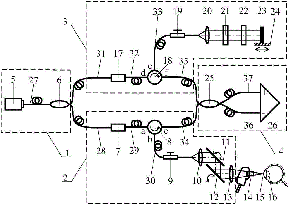
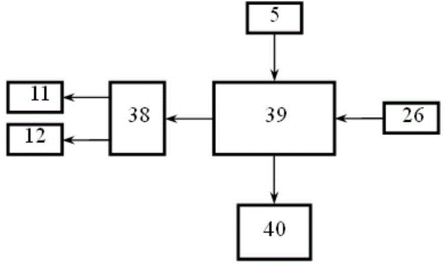
[0033] The system structure of the present invention is as figure 1 , figure 2 As shown, it includes an illumination end 1, a sample arm 2, a reference arm 3, a detection end 4, a jet excitation system 14, a function generation card 38, a data acquisition card 39, and a computer 40.

[0034] figure 1 The middle lighting end 1 is composed of a frequency-sweeping light source 5 , a first single-mode fiber 27 , and a first broadband fiber coupler 6 . The sample arm 2 consists of a first acousto-optic frequency shifter 7, a first optical circulator 8, a first polarization controller 9, a first collimator lens 10, vertical and horizontal scanners 11 and 12, a scanning lens 13, a second to The fourth single-mode optical fiber 28-30 and the eighth single-mode optical fiber 34 are composed. The reference arm 3 is composed of a second acousto-optic...


PUM


Abstract

The invention discloses a system and method for combining cornea elasticity imaging with anterior segment structure imaging. The system is composed of an air injection excitation system and a sweep frequency OCT imaging system capable of carrying out transverse two-dimension scanning. The air injection excitation system provides air flow coaxial with imaging light beams and continuously distributed in the cornea transverse direction to enable the cornea to generate stain. The OCT system is used for imaging for the cornea, and interference spectrum information obtained by the imaging system is used for obtaining the strain distribution of the cornea along with the depth changes through a phase sensitivity algorithm; then two-dimensional or three-dimensional distribution diagram of all parameters of the cornea bio-mechanics can be reconstructed, so that elasticity imaging of the corner is achieved. The system can carry out two-dimensional or three-dimensional imaging on the anterior segment structure. The elasticity information plays an important role in the early diagnosis of the cornea disease, pre-operation estimation in the operation processing process, operative design, process simulation and post-operative evaluation, and is combined with the information of the anterior segment structure so as to provide the more complete basis for the diagnosis and the operative treatment of the ophthalmology disease.

Description

technical field [0001] The present invention relates to corneal optical coherence elastography and anterior segment optical coherence tomography technology, in particular to a method of using frequency-sweeping optical coherence tomography technology combined with phase-sensitive algorithm to analyze corneal biomechanical information and anterior segment structural information Systems and methods for performing in vivo measurements. Background technique [0002] The mechanical properties of living systems are one of the important research contents in the field of biomechanics, and one of the research methods of mechanical properties is based on elastography. Elastic imaging includes two parts: the excitation system and the strain detection imaging system. The excitation system applies dynamic or static stress to the sample to cause it to deform, and the depth-related strain distribution in the deformed region of the sample is obtained by various displacement detection imagin...

Claims


Application Information

Patent Timeline
IPC IPC(8): A61B3/14
Inventor 杨亚良杨彦荣戴云张雨东
Owner INST OF OPTICS & ELECTRONICS - CHINESE ACAD OF SCI
Why Eureka
Try Eureka