
Liquid metal medium forced convection experimental loop

A liquid metal, experimental loop technology, applied in measurement devices, instruments, etc., can solve the problems of harsh operating environment of fusion reactor cladding, and achieve the effect of reducing potential harm

Inactive Publication Date: 2015-03-25
ANHUI SCI & TECH UNIV
View PDF6 Cites 16 Cited by
  • Summary
  • Abstract
  • Description
  • Claims
  • Application Information

AI Technical Summary

Problems solved by technology

However, the operating environment of fusion reactor cladding is harsh (such as strong magnetic field, high temperature, strong corrosion, radiation and stress, etc.), and the flow of liquid metal medium in the cladding and external auxiliary systems will bring many challenging scientific and Technical issues, mainly including: flow characteristics and heat transfer problems of liquid metal medium flowing in the cladding; magnetohydrodynamic (MHD) effect caused by liquid metal medium passing through the magnetic field; liquid metal medium and fusion reactor candidate structures and functions Compatibility of materials; on-line purification of liquid metal impurities in the system and materials science under the synergy of various physical fields (radiation field, temperature field, electromagnetic field and stress, etc.); etc., these liquid metal media will A series of problems are caused, such as the erosion of the medium flow on the transmission pipeline, the corrosion problem of the transmission pipeline under the action of thermal stress caused by the change of medium temperature, the flow characteristics of different mediums in the pipeline affect the long-distance transmission efficiency, and the various conditions in which the medium flows Working conditions and environmental factors affect flow efficiency, etc.

Method used


Image

  • Liquid metal medium forced convection experimental loop

Examples


Embodiment Construction

[0033] The present invention will be further described below by specific embodiment, but this is not limitation of the present invention, those skilled in the art can make various modifications or improvements according to the basic idea of ​​the present invention, but as long as not departing from the basic idea of ​​the present invention, are all within the scope of the present invention.

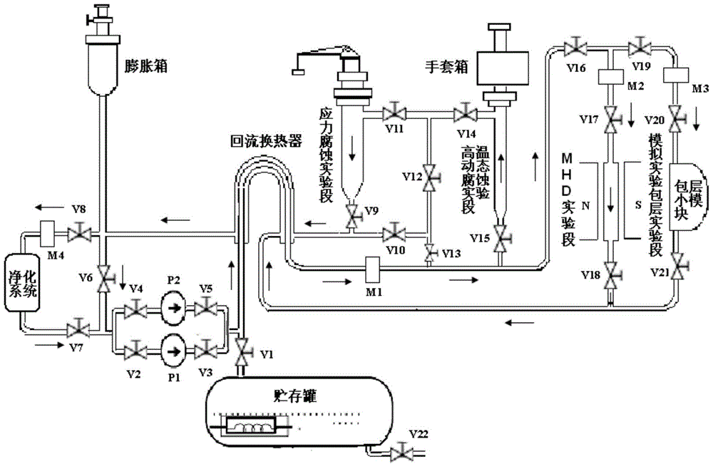
[0034] see figure 1 , liquid metal medium forced convection experimental circuit, its composition mainly includes: a storage tank for storing liquid metal medium, electromagnetic pumps P1 and P2 to drive the flow of liquid metal medium, a purification system for on-line monitoring and purification of impurities, a return heat exchanger, High temperature dynamic corrosion test section, stress corrosion test section, MHD test section (including electromagnet), simulation experiment cladding test section, and related valves V1~V21, flow meters M1, M2, M3, M4, gas system, heating and tempera...


PUM


Abstract

The invention discloses a liquid metal medium forced convection experimental loop. The liquid metal medium forced convection experimental loop comprises a hot area, a cold area and a support system, wherein a pipeline of the hot area and a pipeline of the cold area form the shape of the Arabic numeral eight, and the hot area and the cold area intersect at a reflux heat exchanger. Various experimental sections are arranged in the hot area according to needs and comprise the high-temperature dynamic corrosion experimental section, the stress corrosion experimental section, the MHD experimental section and the simulation experiment blanket experimental section. A liquid metal medium purification system, a power pump, an expansion box and a storage tank are arranged in the cold area. The support system comprises a gas system and a temperature control system, wherein the gas system is used for conducting vacuumizing and argon filling on the experimental loop, and the temperature control system is used for conducting heating and temperature monitoring on the pipelines. The experimental loop can be used for carrying out experiment researches on critical technical problems of blankets according to experimental purposes under the experimental environment where fusion reactor working conditions are created outside reactors.

Description

technical field [0001] The invention relates to a design scheme of an experimental circuit in the field of nuclear industry application and scientific research, in particular to an experimental circuit for forcing convective motion of a liquid metal medium. Background technique [0002] The cladding is the core technology carrier for the application of fusion energy. The cladding (including the first wall) contains lithium-containing materials in its modules, and neutrons react with lithium to generate tritium, which is separated and then fed back into the plasma. At the same time, the neutron energy is extracted through the coolant to drive the generator to generate electricity. Therefore, the main function of the cladding is to convert the energy of fusion particles into usable energy and at the same time proliferate tritium to maintain the fusion reaction. Necessary places for experiments. Obviously, cladding technology is one of the core technologies that determine th...

Claims


Application Information

Patent Timeline
IPC IPC(8): G01D21/02
Inventor 章毛连吴宜灿黄群英许万祥高伟霞秦炎福刘念何恩节官邦贵吕跃凤韩新风高海涛姚洁王娜
Owner ANHUI SCI & TECH UNIV
Learn More