Optical fiber sensing device measuring vibration waveform and vibration position simultaneously and sensing method thereof

A vibration waveform and optical fiber sensing technology, which is applied in measuring devices, measuring ultrasonic/sonic/infrasonic waves, utilizing wave/particle radiation, etc., can solve the problems of total harmonic distortion, increasing the burden of demodulation system, and high sampling frequency, etc. It achieves the effect of reducing the sampling frequency, superior demodulation effect, and facilitating arraying

Active Publication Date: 2015-03-25
TIANJIN UNIVERSITY OF TECHNOLOGY
View PDF4 Cites 8 Cited by
  • Summary
  • Abstract
  • Description
  • Claims
  • Application Information

AI Technical Summary

Problems solved by technology

In October 2008, Gong Mingju proposed the DCM algorithm of triple frequency mixing in Piezoelectricity and Acousto-optic (pp. 538-540). This algorithm requires a higher sampling frequency and increases the burden on the demodulation system.
In May 2012, Li Yang proposed a DCM algorithm based on fundamental frequency mixing in optoelectronic lasers (pp. 933-938). This algorithm can only demodulate small signals
In October 2012, Wang Kai reported the arctangent algorithm in Optoelectronic Laser (pp. 1856-1862), which may have serious total harmonic distortion

Method used


Image

  • Optical fiber sensing device measuring vibration waveform and vibration position simultaneously and sensing method thereof
  • Optical fiber sensing device measuring vibration waveform and vibration position simultaneously and sensing method thereof
  • Optical fiber sensing device measuring vibration waveform and vibration position simultaneously and sensing method thereof

Examples


Embodiment 1

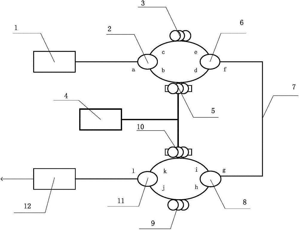
[0034] In this embodiment, the light source is a distributed feedback laser with a wavelength of 1550 nm and a power of 2.3 mw. The two sections of delay fiber are both 25km long, the length of any one of the two Mach-Zehnder interferometers is 8m, and the piezoelectric ceramics wound with 3m optical fibers are placed in the middle of each interference arm. The length of the sensing fiber between two cascaded Mach-Zehnder interferometers is 60km. Assume that the vibration point to be measured is placed 30km away from the first delay fiber. The carrier frequency generated by the signal generator is selected as 1180Hz, the signal sampling frequency in the demodulation circuit is selected as 100KHz, and the signal to be tested is selected as a sine wave with an amplitude of 1 and a frequency of 100Hz. according to Figure 4 It can be concluded that the offset of the waveform on the time axis of the abscissa is 0.00021184, and the relevant parameters set in this embodiment are s...

Embodiment 2

[0036] In this embodiment, the light source is a distributed feedback laser with a wavelength of 1550 nm and a power of 2.3 mw. The two sections of delay fiber are both 25km long, the length of any one of the two Mach-Zehnder interferometers is 8m, and the piezoelectric ceramics wound with 3m optical fibers are placed in the middle of each interference arm. The length of the sensing fiber between two cascaded Mach-Zehnder interferometers is 60km. Assume that the vibration point to be measured is placed 30km away from the first delay fiber. The carrier frequency generated by the signal generator is selected as 1180Hz, the signal sampling frequency in the demodulation circuit is selected as 500KHz, and the signal to be tested is selected as a sine wave with an amplitude of 1 and a frequency of 100Hz. according to Figure 5 It can be concluded that the offset of the waveform on the time axis of the abscissa is 0.00021206, and the relevant parameters set in this embodiment are s...

Embodiment 3

[0038] In this embodiment, the light source is a distributed feedback laser with a wavelength of 1550 nm and a power of 2.3 mw. Both sections of delay fiber are 15km long, and the length of any one interference arm of the two Mach-Zehnder interferometers is 8m. A piezoelectric ceramic wound with a 3m optical fiber is placed in the middle of each interference arm. The length of the sensing fiber between two cascaded Mach-Zehnder interferometers is 60km. Assume that the vibration point to be measured is placed 30km away from the first delay fiber. The carrier frequency generated by the signal generator is selected as 1180Hz, the signal sampling frequency in the demodulation circuit is selected as 500KHz, and the signal to be tested is selected as a sine wave with an amplitude of 1 and a frequency of 100Hz. according to Image 6 It can be concluded that the offset of the waveform on the time axis of the abscissa is 0.00037422, and the relevant parameters set in this embodiment ...


PUM


Abstract

The invention provides an optical fiber sensing device measuring a vibration waveform and a vibration position simultaneously and a sensing method of the optical fiber sensing device. The optical fiber sensing device measuring vibration waveform and vibration position simultaneously and the sensing method of the optical fiber sensing device aim to achieve detection of the vibration waveform and measurement of the position of a vibration point through double cascade type Mach-Zehnder interferometers. According to a sensing portion, the double cascade type Mach-Zehnder interferometers are set up, and the vibration waveform is sensed; according to an analysis portion, a base frequency mixed type arc tangent-differential self-multiplication algorithm is adopted to correctly demodulate the waveform of a vibration signal, and the vibration position is worked out through offset of the waveform. The optical fiber sensing device has the advantages that the vibration waveform and the vibration position of the vibration waveform can be accurately measured; according to an optical path portion, a sensing optical fiber is additional arranged between the double Mach-Zehnder interferometers, modulation and sensing are separated, and therefore the optical fiber sensing device is easily suitable for sensing in various complicated environments; according to a demodulation algorithm portion, based on the base frequency mixing technology, the sampling frequency is reduced, arraying of optical fiber sensing is facilitated according to the arc tangent-differential self-multiplication algorithm, and therefore a demodulation effect is better.

Description

technical field [0001] The invention belongs to the technical field of optical fiber sensing, in particular to an optical fiber sensing device and method for simultaneous measurement of vibration waveform and position. Background technique [0002] Vibration widely exists in industrial activities and people's lives, such as the occurrence of earthquakes, the operation of machine tools in the mechanical industry, the shaking of railways and bridges, etc. In order to realize early prediction of earthquakes, know the working status of components in time, monitor the safety of railways and bridges, and ensure the safety of long-distance oil and power transmission lines, it has very important practical significance. [0003] Optical fiber sensing has wide frequency transmission frequency, large information capacity, and low transmission loss, which is suitable for telemetry and remote control; it is sensitive to changes in the external environment and has excellent sensing perfor...

Claims


Application Information

Patent Timeline
Patent Type & Authority Applications(China)
IPC IPC(8): G01H9/00
Inventor 张爱玲王恺晗
Owner TIANJIN UNIVERSITY OF TECHNOLOGY
Why Eureka
Try Eureka