

Nickel coated carbon fluoride positive electrode material and preparation method thereof
A carbon-fluoride-coated, positive-electrode material technology, applied to the electrodes of primary batteries, battery electrodes, electrical components, etc., can solve problems such as insufficient effects, achieve enhanced hydrophilic and lipophilic properties, stable structure, and improved discharge voltage platform Effect
- Summary
- Abstract
- Description
- Claims
- Application Information
AI Technical Summary
Problems solved by technology
Method used
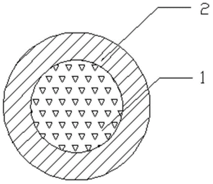
Image

Examples
Embodiment 1
[0044] Take 5 g of fluorinated graphite particles with a fluorine-carbon atomic ratio of 1.03 and a particle size of 5 to 10 μm for electroless nickel plating. The electroless nickel plating process is as follows:
[0045] (1) cleaning
[0046]Add the above-mentioned fluorocarbons to the alcohol-water solution with a volume ratio of alcohol to water of 1:1 and a total volume of 1 L. The temperature is 25° C., the stirring speed is 200 rpm, and the ultrasonic vibration is performed at a frequency of 30 kHz for 5 min.
[0047] The fluorocarbons were centrifuged and rinsed several times with deionized water.
[0048] (2) Sensitization
[0049] Add the cleaned carbon fluoride to the composition of tin protochloride (SnCl 2 2H 2 (0) 4g / L, 37% HCl 4mL / L, OP-101mL / L, the solvent is deionized water, and the volume is in the solution of 1L. The temperature is 25° C., the stirring speed is 200 revolutions per minute, and the time is 2 minutes.
[0050] The fluorocarbons were centr...
Embodiment 2
[0066] Take 20g of fluorinated carbon fiber with a fluorocarbon atomic ratio of 0.85 and a particle size of 10-15 μm, and perform electroless nickel plating. The electroless nickel plating process is as follows:
[0067] (1) cleaning
[0068] Add the above-mentioned fluorocarbons to the alcohol-water solution with a volume ratio of 1:2 and a total volume of 1 L. The temperature is 25° C., the stirring speed is 200 revolutions per minute, the ultrasonic vibration is performed at a frequency of 35 kHz, and the time is 8 min.
[0069] The fluorocarbons were centrifuged and rinsed several times with deionized water.
[0070] (2) Sensitization
[0071] Add the cleaned carbon fluoride to the composition of tin protochloride (SnCl 2 2H 2 (0) 7g / L, 37% HCl 5mL / L, each 0.5mL / L of sucrose ester and OP-10, the solvent is deionized water, and the volume is in a solution of 1L. The temperature is 25° C., the stirring speed is 400 revolutions per minute, and the time is 2 minutes.
[...
PUM
| Property | Measurement | Unit |
|---|---|---|
| thickness | aaaaa | aaaaa |
| particle diameter | aaaaa | aaaaa |
| thickness | aaaaa | aaaaa |
Abstract
Description
Claims
Application Information