Oil shale semicoke fluidized combustion circulation gas heating technology
A technology for oil shale semi-coke and circulating gas, which is applied in the petroleum industry, direct heating dry distillation, coke oven and other directions to achieve the effect of solving environmental problems
- Summary
- Abstract
- Description
- Claims
- Application Information
AI Technical Summary
Problems solved by technology
Method used
Image

Examples
Embodiment Construction
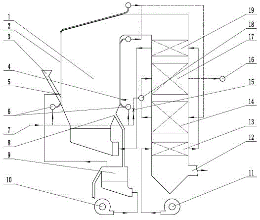
[0020] The present invention will be further described below using the accompanying drawings and examples.
[0021] refer to figure 1 , the oil shale semi-coke fluidized combustion cycle gas heating process of the present invention, the >0~15mm oil shale semi-coke is sent into the fluidized bed furnace 1 from the feed port 3, and the remaining gas is sent from the remaining gas burner 4 Fluidized bed furnace 1, semi-coke and residual gas enter fluidized bed furnace 1 and burn at a low temperature of 850~950°C; part of the heat released by combustion of semi-coke and residual gas in fluidized bed furnace 1 heats the membrane wall around the furnace The circulating gas flowing in the heat exchanger 2, part of the flue gas produced by combustion flows through the high-temperature air preheating tubular heat exchanger 19, the high-temperature gas heating tubular heat exchanger 17, and the medium-temperature gas heating tubular heat exchanger 14 and the low-temperature air preheat...
PUM
 Abstract
Description
Claims
Application Information
PatSnap Eureka turns technology decisions into work you can execute. Powered by our Innovation Knowledge Graph, it runs expert workflows across engineering, life sciences, materials and intellectual property. Get your review-ready output in minutes.


