Laser stimulated emission depletion (STED) and three-dimensional superresolving differential confocal imaging method and device

A laser stimulated emission, differential confocal technology, applied in the direction of the use of optical devices, measuring devices, instruments, etc., can solve the problems of limited applications, achieve the effects of improving lateral resolution, suppressing common mode noise, and improving linearity

Active Publication Date: 2015-04-01
BEIJING INSTITUTE OF TECHNOLOGYGY
View PDF6 Cites 13 Cited by
  • Summary
  • Abstract
  • Description
  • Claims
  • Application Information

AI Technical Summary

Problems solved by technology

Unfortunately, although the patents "Differential Confocal Scanning Detection Method with High Spatial Resolution" and "Super-resolution Laser Polarization Differential Confocal Imaging Method and Device" make the axial resolution reach the nanometer level, their lateral resolution The force can only break through about 30% of the classical diffraction lateral resolution, which limits its application in fields requiring high lateral resolution

Method used


Image

  • Laser stimulated emission depletion (STED) and three-dimensional superresolving differential confocal imaging method and device
  • Laser stimulated emission depletion (STED) and three-dimensional superresolving differential confocal imaging method and device
  • Laser stimulated emission depletion (STED) and three-dimensional superresolving differential confocal imaging method and device

Examples


Embodiment 1

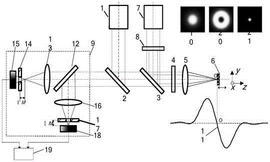
[0038] Such as figure 1 As shown, the laser stimulated emission loss three-dimensional super-resolution differential confocal imaging method, the test steps are as follows:

[0039] First, the wavelength emitted from the excitation laser system 1 is λ 1 After being reflected by the first dichroic mirror 2, the parallel light beam passes through the second dichroic mirror 3 and the quarter-wave plate 4 and is focused on the surface of the tested sample 6 by the objective lens 5. The light (or excited fluorescence) passes through the objective lens 5, the quarter-wave plate 4, the second dichroic mirror 3 and the first dichroic mirror 2 again, and enters the differential confocal detection system 9; A pinhole 14 and a first detector 15 are placed at the front-focus position of the first condenser lens 13 at +M, a second pinhole 17 and a second detector 18 are placed at the post-focus position of the first condenser lens 16 at -M, and the distance M corresponds to The optically...

Embodiment 2

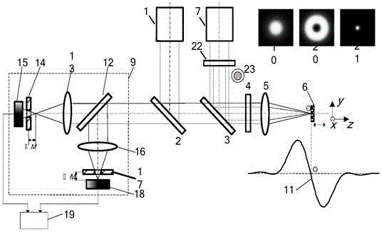
[0045] Such as figure 2 As shown, the annular beam shaping system 22 may be an annular pupil filter, a binary optical diffraction device with an annular phase distribution, etc., and shapes the quenched laser beam into an annular beam 23 . All the other measuring methods are the same as in Example 1.

Embodiment 3

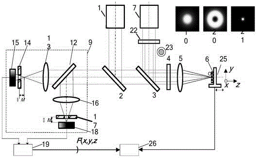
[0047] Such as image 3 As shown, a schematic diagram of an embodiment of a laser stimulated emission loss three-dimensional super-resolution differential confocal imaging device, the principle of which is:

[0048] First, the sample 6 to be tested is placed on the scanning table 25. The scanning table 25 adopts a macro-micro combination method, and a micro-displacement two-dimensional table based on a piezoelectric ceramic driver PZT and a capacitive sensor is integrated on the x-y macro table. , start the measurement software in the main control computer 26.

[0049] The parallel light beam emitted by the excitation laser system 1 is reflected by the first dichroic mirror 2, passes through the second dichroic mirror 3 and the quarter-wave plate 4, and then is focused on the surface of the sample 6 by the objective lens 5, and the band reflected by the sample 6 is The light (or excited fluorescence) with sample information passes through the objective lens 5, the quarter-wav...


PUM


Abstract

The invention belongs to the technical field of optical precise imaging test, and relates to a laser stimulated emission depletion (STED) and three-dimensional superresolving differential confocal imaging method and device. The method and device are characterized in that the laser differential confocal detecting technology and the laser STED imaging technology are organically integrated, the laser differential confocal technology is performed to improve the axial resolution capacity, and while the STED technology is performed to improve the transverse solution capacity, so that the spatial resolution capacity of the system can be improved. The device comprises an excitation laser system, a first dichroic mirror, a quarter-wave plate, an objective lens, a sample, a scanning workbench, a quenching laser system, a beam shaping system, a second dichroic mirror, a differential confocal detecting system and a data processing system. The method and device have an extensive application prospect in the micro-nano technical field with the high spatial resolution three-dimensional superresolving imaging and detecting capacities.

Description

technical field [0001] The invention belongs to the technical field of optical precision imaging testing, and relates to a laser stimulated emission loss three-dimensional super-resolution differential confocal imaging method and device, which can be used for three-dimensional super-resolution imaging and detection of nanoscale geometric parameters in the field of micro-nano technology. technical background [0002] Confocal microscopy is unique in the field of high-resolution optical microscopic detection due to its unique longitudinal tomographic imaging capabilities and the advantages of being easy to combine with super-resolution technology, and plays an extremely important role in nanoscale imaging and detection . [0003] At present, in the study of improving the resolution of confocal microscopy imaging, differential confocal microscopy, biaxial confocal microscopy, confocal interference microscopy, 4π confocal microscopy and stimulated emission depletion microscopy (...

Claims


Application Information

Patent Timeline
Patent Type & Authority Applications(China)
IPC IPC(8): G01B11/24G01B11/00
Inventor 邱丽荣赵维谦王允
Owner BEIJING INSTITUTE OF TECHNOLOGYGY
Why Eureka
Try Eureka