Laser device for outputting flattened beams

A flat-top beam and laser technology, applied in the laser field, can solve the problems of large loss and large loss of the shaping system, and achieve the effects of low loss, high filling factor and simple structure

Inactive Publication Date: 2015-04-08
SHANGHAI INST OF OPTICS & FINE MECHANICS CHINESE ACAD OF SCI
View PDF3 Cites 4 Cited by
  • Summary
  • Abstract
  • Description
  • Claims
  • Application Information

AI Technical Summary

Problems solved by technology

These methods are used to shape the beam by inserting optical devices into the external optical path of the laser, which causes a relatively large loss, and the more complex the shaping system, the greater the loss

Method used


Image

  • Laser device for outputting flattened beams
  • Laser device for outputting flattened beams
  • Laser device for outputting flattened beams

Examples


Embodiment Construction

[0015] The present invention will be further described below in conjunction with the accompanying drawings and embodiments, but the protection scope of the present invention should not be limited thereby.

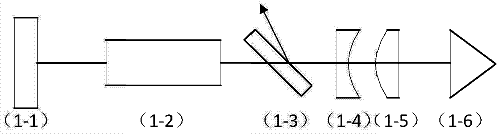
[0016] Such as figure 1 As shown, the laser output flat-hat beam of the present invention includes a reflective cavity mirror 1-1, a gain medium 1-2, a polarizer 1-3, a phase adjustment mirror 1-4, and a compensation lens 1 placed in sequence on the same optical axis. -5 and Porro Prisms 1-6. The reflective cavity mirror 1-1, gain medium 1-2, polarizer 1-3, phase adjustment mirror 1-4, compensation lens 1-5 and Porro prism 1-6 constitute a laser resonant cavity. The angle between the polarizer 1-3 and the optical axis is Brewster's angle, and the phase adjustment mirror 1-4 is a plano-convex lens or a plano-concave lens made of birefringent material. The compensation lens 1-5 is a plano-concave lens or a plano-convex lens, which adopts an isotropic medium or a cubic cryst...


PUM


Abstract

The invention relates to a laser device for outputting flattened beams. The laser device comprises a reflection cavity mirror, a gain medium, a polarizing film, a phase adjustment mirror, a compensating lens and a Porro prism. The laser device utilizes a cavity to place the phase adjustment mirror, and the phase delay of endovascular laser is modulated radially through the polarizing film, the phase adjustment mirror and the Porro prism, so that the radial variation of coupling output rate of the polarizing film is realized, and the laser emergent through the polarizing film is a flattened beam with a flat middle part. Meanwhile, the compensating lens is adopted to eliminate the lens effect caused by inserting the phase adjustment mirror into the laser cavity. The laser device is simple in structure, less in loss, high in efficiency, and high in filling factors of the outputted beams.

Description

technical field [0001] The invention belongs to the technical field of lasers, in particular to a laser for shaping and homogenizing the spatial distribution of output beams in a cavity. Background technique [0002] The energy distribution of the traditional laser output beam is a non-uniform Gaussian spatial distribution. In laser processing, cutting and welding, biomedical engineering and other technical fields, the non-uniform distribution of laser energy will cause local temperature rise and destroy material properties. At the same time, the inhomogeneity of the input beam in the high-power laser system will lead to nonlinear effects such as B integral, which will cause the beam quality to deteriorate, and it will easily cause the local power density to be too high, thus causing damage to the laser medium. Moreover, the filling factor of the Gaussian beam is low and cannot guarantee high energy extraction efficiency, which restricts the efficiency of the amplification ...

Claims


Application Information

Patent Timeline
Patent Type & Authority Applications(China)
IPC IPC(8): H01S3/106
Inventor 孟俊清杨海龙谢银陈苏园陈卫标
Owner SHANGHAI INST OF OPTICS & FINE MECHANICS CHINESE ACAD OF SCI
Why Eureka
Try Eureka