Coal-fired boiler facilities and coal drying method in coal-fired boiler facilities

A technology for coal-fired boilers and coal drying, applied in combustion equipment, combustion methods, lighting and heating equipment, etc., can solve problems such as mixing in and impact on the performance of waste gas treatment equipment, to improve efficiency, suppress efficiency reduction, and suppress hydrocarbon components the effect of

Active Publication Date: 2015-04-08
MITSUBISHI HEAVY IND LTD
View PDF7 Cites 2 Cited by
  • Summary
  • Abstract
  • Description
  • Claims
  • Application Information

AI Technical Summary

Problems solved by technology

If such high-temperature combustion exhaust gas is used as a heat carrier to dry coal, there is a problem that hydrocarbon components volatilize from the coal and mix into the exhaust gas during the process, which will negatively affect the performance of the exhaust gas treatment equipment on the downstream side.

Method used


Image

  • Coal-fired boiler facilities and coal drying method in coal-fired boiler facilities
  • Coal-fired boiler facilities and coal drying method in coal-fired boiler facilities
  • Coal-fired boiler facilities and coal drying method in coal-fired boiler facilities

Examples


no. 1 approach

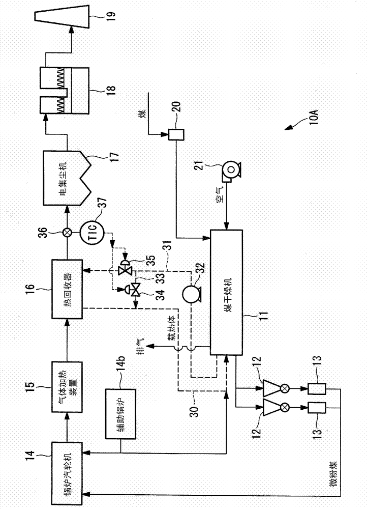
[0051] Below, use figure 1 A first embodiment of the present invention will be described.

[0052] Such as figure 1 As shown, the coal-fired boiler equipment 10A mainly includes a coal dryer 11, a coal hopper 12, a coal mill 13, a boiler steam turbine (boiler) 14, a gas heating device 15, a heat recovery device 16, an electric dust collector 17, and a desulfurization device 18 and chimney 19.

[0053]The coal pulverized by the coal pulverizer 20 is fed into the coal dryer 11, and the coal dryer 11 dries the coal by a structure described in detail later while conveying the coal using air fed by the blower 21 as a transport gas.

[0054] The coal hopper 12 temporarily stores the coal dried by the coal dryer 11 .

[0055] The coal mill 13 pulverizes the coal supplied from the coal hopper 12 to form pulverized coal of a predetermined particle size.

[0056] The pulverized coal pulverized by the coal mill 13 is sent to the boiler turbine 14, where it is mixed with combustion ai...

no. 2 approach

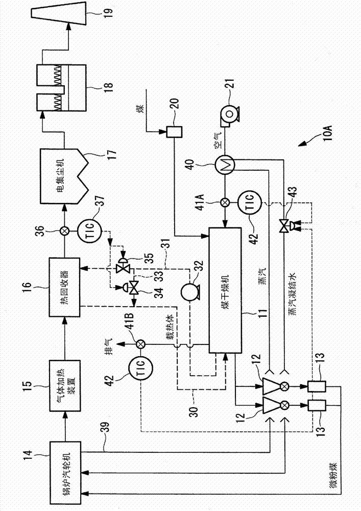
[0093] Next, a second embodiment of the present invention will be described. In the second embodiment described below, the same reference numerals are assigned to the same configurations as those of the first embodiment in the drawings, and their descriptions are omitted, and differences from the first embodiment are mainly described. illustrate.

[0094] Such as Figure 5 As shown, the coal-fired boiler equipment 10B of this embodiment mainly includes a coal dryer 11, a coal hopper 12, a coal mill 13, a boiler steam turbine 14, a gas heating device 15, a heat recovery device 16, an electric dust collector 17, and a desulfurization device 18 and chimney 19.

[0095] In this embodiment, the coal pulverized by the coal pulverizer 20 is fed into the coal dryer 11, and the coal dryer 11 uses the second gas heating device 60 to heat the air sent from the blower 21 as heating air. The heated air is used as transport gas to transport the coal, and the heat of the heated air dries ...

no. 3 approach

[0117] Next, a third embodiment of the present invention will be described. In the third embodiment described below, the same reference numerals are assigned to the same configurations as those of the first and second embodiments in the drawings, and their descriptions are omitted. Differences of the embodiments will be described.

[0118] The structure of the third embodiment shown below can also be added to Figure 1 to Figure 8 Either structure shown. Below, shown in Figure 5 An example of the structure of this embodiment is added to the shown structure.

[0119] Such as Figure 9 As shown, the coal-fired boiler equipment 10C of this embodiment is in Figure 5 The shown coal-fired boiler facility 10B further includes a gypsum separator 65 and a spray dryer 66 in addition to the configuration.

[0120] The gypsum separator 65 filters the wastewater from the desulfurization device 18 and separates it into a gypsum component and a filtrate. The filtrate (drainage) obta...


PUM


Abstract

Coal is properly dried and the efficiency of a boiler is increased while suppressing any reduction in efficiency of the boiler and the generation of hydrocarbon gas components. Employed are a coal dryer that dries coal, a boiler in which the coal that is dried in the coal dryer is mixed with air for combustion and burned, an air heater that heats the air for combustion that is supplied to the boiler using combustion exhaust gas discharged from the boiler, a precipitator that collects dust included in the combustion exhaust gas, a desulfurization plant that performs a desulfurization process on the combustion exhaust gas, and heat recovery equipment that heats a heating medium using the combustion exhaust gas. The coal dryer dries the coal using the heat energy of the heating medium that has been heated in the heat recovery equipment.

Description

technical field [0001] The invention relates to coal-fired boiler equipment and a coal drying method in the coal-fired boiler equipment. Background technique [0002] In power generation facilities equipped with coal-fired boilers and steam turbines (hereinafter referred to as boilers as appropriate), coal used as fuel is classified into high-grade, medium-grade, and low-grade grades according to the water content and degree of coalification. [0003] Low-grade coal such as lignite, which has a high water content and low degree of coalification, has a lower calorific value than high-grade coal, so it is also preferable to dry it before putting it into the boiler in order to improve the combustion efficiency of the boiler. [0004] In this regard, coal has been dried by heating with steam extracted from a boiler. [0005] In addition, it has been proposed to dry coal by heating coal using combustion exhaust gas discharged from an economizer (economizer) of a boiler or an out...

Claims


Application Information

Patent Timeline
Patent Type & Authority Applications(China)
IPC IPC(8): F23K1/00F23J15/00F23L15/00
CPCF23J2217/102F23L15/04F23J15/04F23K2201/20F23K2201/10F23J15/022F23G5/04F23K1/04B03C3/017Y02E20/34Y02P80/15
Inventor 杉田觉本城新太郎冈本卓也
Owner MITSUBISHI HEAVY IND LTD
Why Eureka
Try Eureka