Forming device and method for end socket with baffle

A forming method and head technology, which is applied in the field of one-step general rotation forming technology of thin-walled aluminum alloy heads, can solve the problems of difficulty in ensuring the shape accuracy of workpieces, cumbersome multi-pass trajectory planning, and small support rigidity, etc. Wrinkle defects, solve the flange wrinkle problem, and improve the effect of supporting rigidity

Active Publication Date: 2015-04-22
SHANGHAI JIAO TONG UNIV
View PDF8 Cites 7 Cited by
  • Summary
  • Abstract
  • Description
  • Claims
  • Application Information

AI Technical Summary

Problems solved by technology

The disadvantage is that the size of the component is large, and it is difficult to guarantee the shape accuracy of the workpiece without a mandrel; the contact between the forming rod and the flange is a point contact, the support rigidity is small, and the wrinkling is serious during the forming process, which requires multiple passes. Forming will bring about the problem of excessive wall thickness reduction; the spinning roller and the forming roller need different control systems to control them separately, the mechanism is complex, and the multi-pass trajectory planning is cumbersome

Method used


Image

  • Forming device and method for end socket with baffle
  • Forming device and method for end socket with baffle
  • Forming device and method for end socket with baffle

Examples


Embodiment 1

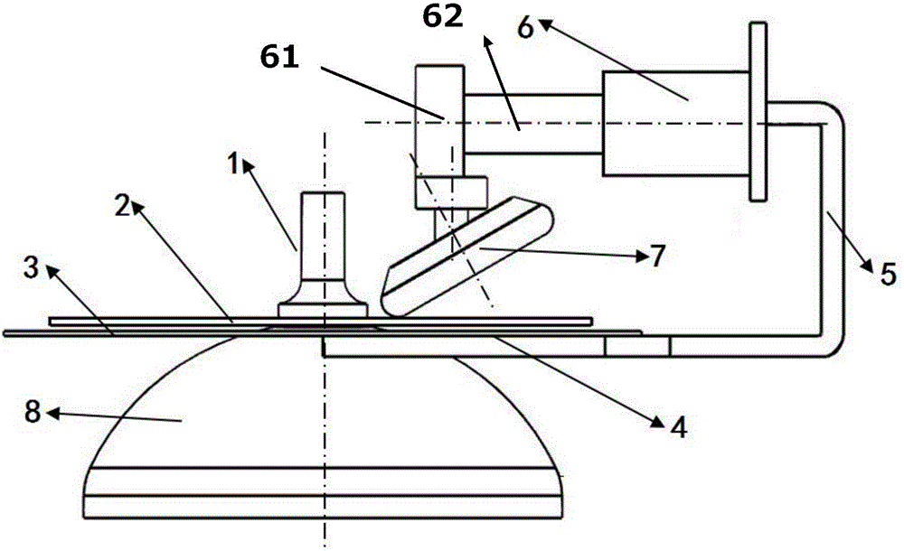
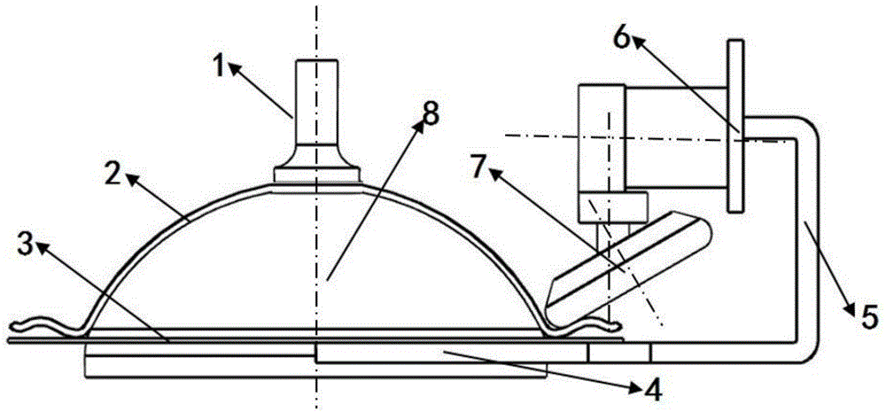
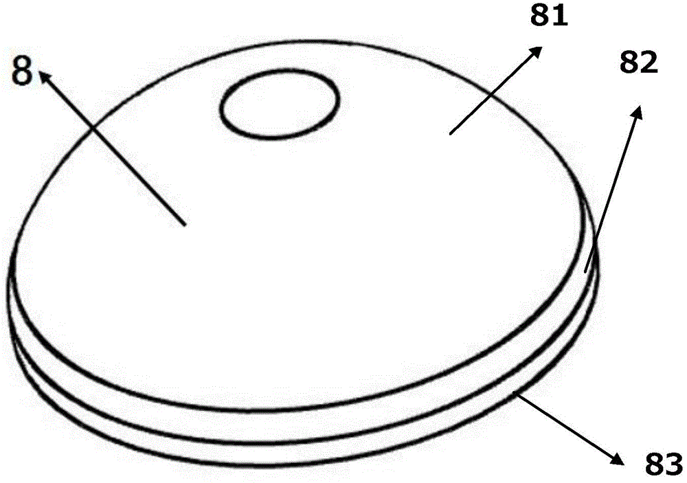
[0035] In this embodiment, the diameter of the upper opening of the mandrel 8 is 100mm, the diameter of the lower opening is 20.6mm, the height is 41mm, and the fillet radius of the transition zone is 14mm; the pressing force of the tail top 1 is 4000KN; the material of the slab 2 is 2024-O state aluminum alloy, with a diameter of 140mm and a thickness of 1mm; the thickness of the baffle plate 3 is 5mm, the inner diameter is 102m, and the outer diameter is 160mm; The C-shaped cantilever 5 is rigidly connected to ensure the stable and synchronous feeding of the baffle plate 3 and the rotary wheel 7 in the axial direction during the spinning process; the diameter of the rotary wheel 7 is 100mm, the radius of the fillet is 10mm, and the installation angle of the rotary wheel is 30°; , the mold gap between the rotary wheel 7 and the mandrel 8 is 1mm during forming; the gap between the rotary wheel 7 and the baffle 3 is 3mm, the required feed rate for forming the spherical crown are...

Embodiment 2

[0037]In this embodiment, the diameter of the upper opening of the mandrel 8 is 300 mm, the diameter of the lower opening is 60 mm, the height is 120 mm, and the radius of the fillet transition zone is 40.8 mm; the diameter of the slab 2 is 400 mm; the inner diameter of the baffle plate 3 is 302 mm, and the outer diameter is 420mm; Other implementations are the same as in Example One. The diameter-thickness ratio of the formed head part in this embodiment is 300, the bow-to-height ratio is 0.4, and the maximum wall thickness reduction rate after forming is 14.4%. It is superior to the head parts obtained by the multi-pass spinning process.


PUM

PropertyMeasurementUnit
thicknessaaaaaaaaaa
diameteraaaaaaaaaa
radiusaaaaaaaaaa

Abstract

The invention discloses a forming device and method for an end socket with a baffle. The device comprises a C-shaped cantilever, a tool base, a rotary wheel, a rotary wheel frame, a baffle frame and a telescopic arm, wherein the tool base and the baffle frame are fixedly arranged at the two ends of the C-shaped cantilever respectively; the telescopic arm is movably arranged in the tool base; the rotary wheel frame is movably arranged at one end of the telescopic arm; the rotary wheel is movably arranged at the bottom of the rotary wheel frame. The forming device and method have the advantages that the problem that due to shear spinning and pulling thinning action of a multi-pass forming rotary wheel in the traditional process, the wall thickness is decreased too much is avoided, the wrinkling defect is overcome effectively, and evenness of the wall thickness is improved remarkably; the bearing stiffness of a flange is further improved in the forming process, and the stress condition of a plate in the forming process is effectively improved; the problems that multiple passes exist and shear spinning and conventional spinning are mixed in the traditional forming process of the end socket are solved; the novel process mechanism is easy to implement.

Description

technical field [0001] The invention relates to a forming process in the technical field of plastic forming, in particular to a one-pass general rotation forming process for a thin-walled aluminum alloy head with a baffle. Background technique [0002] The head is an important part widely used in boilers, pressure vessels, chemical containers, rocket shells, nuclear reactors and artificial satellites, etc., and its specifications are developing in the direction of large-scale and thin-walled. The traditional petal splicing method is inefficient and the overall mechanical properties of the head are not uniform. The spinning method can obtain integrally seamless rotary parts. Spinning belongs to the problem of single-point continuous deformation. During the forming process, the tail top presses the sheet material on the mandrel, and under the action of friction, it rotates at high speed with the spindle of the machine tool. The spinning wheel moves longitudinally and laterally...

Claims


Application Information

Patent Timeline
Patent Type & Authority Applications(China)
IPC IPC(8): B21D22/16
CPCB21D22/16
Inventor 史敏孔庆帅赵亦希于忠奇王皓余海东
Owner SHANGHAI JIAO TONG UNIV
Why Eureka
Try Eureka