Imaging flow cytometer

A flow cytometer and imaging technology, applied in the field of optical instruments, can solve the problems of low energy utilization, high cost, complex structure, etc., and achieve the effects of high energy utilization, simple structure and accurate measurement

Inactive Publication Date: 2015-04-22
CHANGCHUN INST OF OPTICS FINE MECHANICS & PHYSICS CHINESE ACAD OF SCI
View PDF7 Cites 9 Cited by
  • Summary
  • Abstract
  • Description
  • Claims
  • Application Information

AI Technical Summary

Problems solved by technology

[0008] In order to solve the problems of low energy utilization rate, complex structure and high cost of defocus and velocity measurement existing in the existing imaging flow cytometer system, the present invention provides an imaging flow cytometer

Method used


Image

  • Imaging flow cytometer
  • Imaging flow cytometer
  • Imaging flow cytometer

Examples


Embodiment Construction

[0037] The present invention will be described in further detail below in conjunction with the accompanying drawings.

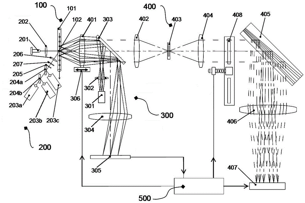
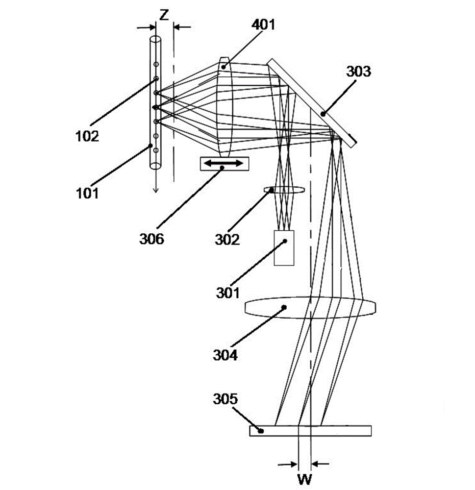
[0038] Such as figure 1 As shown, the imaging flow cytometer of the present invention is based on the laser backscattering spot imaging principle, and at the same time introduces a polarization optical system to complete the speed detection of the sample 102 to be tested and the autofocus function of the cytometer, and some information about the sample 102 to be tested can be obtained. Richer biological information is mainly composed of sample sampling unit 100 , laser light source 200 , speed measurement-focus unit 300 , imaging unit 400 and central control unit 500 .

[0039] The sample sampling unit 100 is mainly composed of a sampling device 101 and a sample to be tested 102. In the sampling device 101, the samples to be tested 102 pass through the imaging detection area one by one at a uniform speed. The imaging detection area refers to a certain area on...


PUM

PropertyMeasurementUnit
poweraaaaaaaaaa
wavelengthaaaaaaaaaa

Abstract

The invention provides an imaging flow cytometer and relates to the field of optical instruments in biology and medical science. The problems that an existing imaging flow cytometer system is low in energy use rate in defocusing distance and speed measurement, complex in structure and high in cost are solved. A polarization optical system is introduced, richer biological information relative to samples to be measured can be acquired, and the imaging flow cytometer is mainly composed of a sample injection unit, a laser source, a speed measurement-focusing unit, an imaging unit and a central control unit. Meanwhile, based on the laser back scattering light spot imaging principle, the speed detection function of the samples to be measured and the automatic focusing function of the cytometer are finished. Through analysis of sequence signals of light signal intensity of the samples to be measured in different sensing positions of an array optical sensor and analysis of distribution of light signal intensity of the detection face of the sensor, the cell movement speed and the defocusing distance can be acquired at the same time, measurement is more accurate and visual, the energy use rate and the signal to noise ratio are higher by the adoption of a laser back scattering mode, and a single optical path detection structure is simpler.

Description

technical field [0001] The invention relates to the technical field of biological and medical optical instruments, in particular to an imaging flow cytometer. Background technique [0002] Flow cytometry is a technique for rapid quantitative analysis and sorting of cells or other biological particles (such as microspheres, bacteria, small model organisms, etc.) arranged in a single row in a liquid flow. In the fields of biology and medicine, when a large number of cells need to be scanned, the flow cytometer completely sacrifices the spatial resolution to obtain a high detection speed, tens of thousands of cells per second. Imaging flow cytometry can not only obtain population analysis data of a large number of cells, but also can see cell images in real time, and the analysis results of each step can be confirmed by images. Compared with traditional flow cytometers, imaging flow cytometers have greater advantages when it is necessary to obtain cell morphology and internal ...

Claims


Application Information

Patent Timeline
Patent Type & Authority Applications(China)
IPC IPC(8): G01N15/14
Inventor 李灿孙强
Owner CHANGCHUN INST OF OPTICS FINE MECHANICS & PHYSICS CHINESE ACAD OF SCI
Why Eureka
Try Eureka