
Portable radar speed measurement machine

A portable radar and speed measuring machine technology, applied in measurement devices, radio wave measurement systems, reflection/re-radiation of radio waves, etc. Reduce measurement errors, avoid errors, and facilitate playback and analysis

Inactive Publication Date: 2015-04-22
NO 63921 UNIT OF PLA
View PDF5 Cites 0 Cited by
  • Summary
  • Abstract
  • Description
  • Claims
  • Application Information

AI Technical Summary

Problems solved by technology

The traditional radar speed measuring machine subsystem belongs to a part of the radar tracking loop and is inseparable from other radar subsystems. Affected by the bandwidth of the closed-loop tracking loop, when the tracking target has a large maneuver, the phase of the measurement echo will be distorted. A simple The fast Fourier transform will cause wrong speed measurement results; at the same time, the invariant embedding method needs a long time to accumulate and can only obtain the average ambiguity in the accumulation interval. When the speed changes suddenly, it is difficult to quickly return to normal and cannot be applied to accuracy and Areas with high robustness requirements

Method used

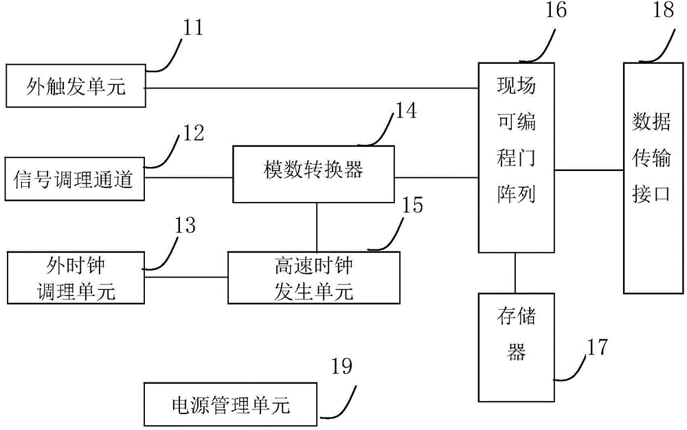
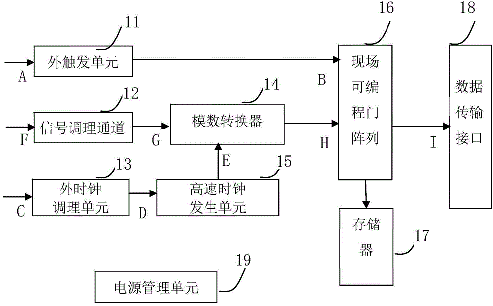

Image

  • Portable radar speed measurement machine
  • Portable radar speed measurement machine
  • Portable radar speed measurement machine

Examples


Embodiment Construction

[0022] In order to further explain the technical means and effects that the present invention takes to achieve the intended purpose of the invention, below in conjunction with the accompanying drawings and preferred embodiments, the specific implementation methods, steps, structures, features and details of the portable radar speed measuring machine proposed according to the present invention will be described below. Its efficacy is described in detail.

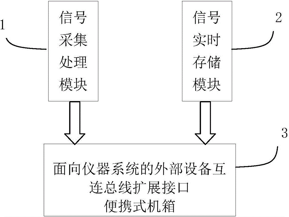
[0023] see figure 1 As shown, it is a structural block diagram of the portable radar speed measuring machine of the present invention. The portable radar speed measuring machine includes a signal acquisition and processing module 1, a signal real-time storage module 2 and a portable chassis 3 for an instrument system-oriented external device interconnection bus expansion interface, and the signal acquisition and processing The module 1 and the signal real-time storage module 2 are connected to each other through the bus of th...


PUM


Abstract

The invention relates to a portable radar speed measurement machine which comprises a pulse signal acquisition processing module, a signal real-time storage module and a portable machine case. The pulse signal acquisition processing module and the signal real-time storage module are connected through a bus of the portable machine case. The portable radar speed measurement machine can achieve high-speed sampling and real-time recording of radar echo signals and facilitates subsequent playback analysis. The portable radar speed measurement machine can normally work under the condition of 220 V alternating current, can be conveniently connected with radar intermediate frequency through a radio antenna interface and becomes an additional open loop branch circuit of a radar during connection, the capacity of adapting to target maneuvering situation is improved by means of a motion model constrained instantaneous frequency measurement method, the high-accuracy speed measurement of the radar to a high-dynamic target can be achieved, and meanwhile closed loop tracking of an original radar system is not influenced.

Description

technical field [0001] The invention relates to the field of radar measurement, in particular to a portable radar speed measuring machine. Background technique [0002] The traditional pulse radar speed measuring machine is fixedly connected with the whole radar as a part of the radar system. Its main principle is: coherently accumulate the received echoes, use fast Fourier transform to do spectrum analysis, and estimate the Doppler frequency , and then use the ranging data and the invariant embedding method to solve the ambiguity, and then obtain the velocity estimation. The traditional radar speed measuring machine subsystem belongs to a part of the radar tracking loop and is inseparable from other radar subsystems. Affected by the bandwidth of the closed-loop tracking loop, when the tracking target has a large maneuver, the phase of the measurement echo will be distorted. A simple The fast Fourier transform will cause wrong speed measurement results; at the same time, th...

Claims


Application Information

Patent Timeline
IPC IPC(8): G01S13/58
CPCG01S13/581
Inventor 张艳郝世锋张兵单洪春李楠王伟刘森
Owner NO 63921 UNIT OF PLA
Learn More