
Intravascular imaging system and method

An imaging system and imaging method technology, which is applied in the field of intravascular imaging, can solve the problems of inability to meet in vivo interventional imaging, real-time imaging, and low tissue energy density, and achieve increased luminous flux density, high repetition rate, and improved imaging signal-to-noise than the effect

Active Publication Date: 2015-04-29
SHENZHEN INST OF ADVANCED TECH
View PDF5 Cites 36 Cited by
  • Summary
  • Abstract
  • Description
  • Claims
  • Application Information

AI Technical Summary

Problems solved by technology

[0007] Existing endoscopic devices emit divergent beams, and the energy density reaching the tissue is low. Generally, pulse energy in the order of mJ is required to obtain a photoacoustic signal with sufficient signal-to-noise ratio.
At present, the tunable pulse laser that can provide mJ energy has a repetition rate of only 10-20Hz, so the current intravascular photoacoustic system generally uses a 10Hz tunable pulse laser. When each frame is composed of 200 lines, the photoacoustic imaging The speed is ~0.05 frames per second, which is far from meeting the requirements of in vivo interventional imaging
It can be seen that under the current laser technology, the existing intravascular photoacoustic imaging system design cannot achieve real-time imaging, which has become one of the key factors limiting the clinical application of intravascular photoacoustic technology

Method used


Image

  • Intravascular imaging system and method
  • Intravascular imaging system and method
  • Intravascular imaging system and method

Examples


Embodiment Construction

[0043] The following will clearly and completely describe the technical solutions in the embodiments of the present invention with reference to the accompanying drawings in the embodiments of the present invention. Obviously, the described embodiments are only some, not all, embodiments of the present invention. Based on the embodiments of the present invention, all other embodiments obtained by persons of ordinary skill in the art without making creative efforts belong to the protection scope of the present invention.

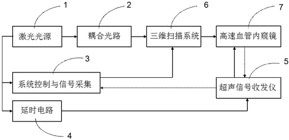
[0044] Such as figure 1 As shown, the embodiment of the present invention provides an intravascular imaging system. The intravascular imaging system includes: a laser light source 1, a coupling optical path 2, a signal acquisition and control system 3, a delay circuit 4, an ultrasonic signal transceiver 5, A three-dimensional scanning system 6 and a photoacoustic / ultrasonic endoscopic device 7 .

[0045] The laser light source 1 is a tunable pulse laser, whic...


PUM

PropertyMeasurementUnit
Frequencyaaaaaaaaaa

Abstract

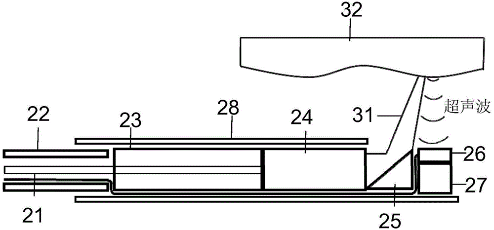
The invention provides an intravascular imaging system and method. The intravascular imaging system comprises a laser source, a coupling optical path, a signal acquisition and control system, a time-delay circuit, an ultrasonic signal transceiver, a three-dimensional scanning system and an opto-acoustic / ultrasonic vascular endoscope device; pulse laser emitted by the laser source is guided into the opto-acoustic / ultrasonic vascular endoscope device through the coupling optical path and the three-dimensional scanning system; the pulse laser obliquely enters to a vascular wall to excite an opto-acoustic signal; a synchronous triggering signal emitted by the laser source enters the ultrasonic signal transceiver; the ultrasonic signal transceiver is used for controlling the opto-acoustic / ultrasonic vascular endoscope device to emit and receive the ultrasonic signal according to the synchronous triggering signal; the signal acquisition and control system is used for receiving the opto-acoustic signal and the ultrasonic signal from the opto-acoustic / ultrasonic vascular endoscope device through the ultrasonic signal transceiver and carrying out three-dimensional reconstruction according to the opto-acoustic signal and the ultrasonic signal to generate a three-dimensional image and a cross section image of intravascular tissues. According to the intravascular imaging system and method, the imaging speed can be improved.

Description

technical field [0001] The invention relates to intravascular imaging technology, in particular to an intravascular imaging system and method. Background technique [0002] Intravascular photoacoustic imaging technology uses the light absorption comparison of tissue itself and photoacoustic spectroscopy to detect the chemical composition of plaques, and combines ultrasound imaging technology to obtain intravascular structural information, which has the potential to become an early imaging identification of vulnerable plaques. important new technology. However, at present, the imaging speed of intravascular ultrasound imaging systems reported in literature and patents is generally ~0.05 frames per second, which is far from meeting the requirements of clinical use. [0003] The speed of intravascular photoacoustic imaging is currently mainly limited by the repetition rate of the pulsed light source. The repetition frequency of the tunable pulse light source is inversely prop...

Claims


Application Information

Patent Timeline
IPC IPC(8): A61B5/00
CPCA61B5/0095A61B8/5246A61B2017/00154
Inventor 宋亮李岩龚小竞林日强
Owner SHENZHEN INST OF ADVANCED TECH
Learn More