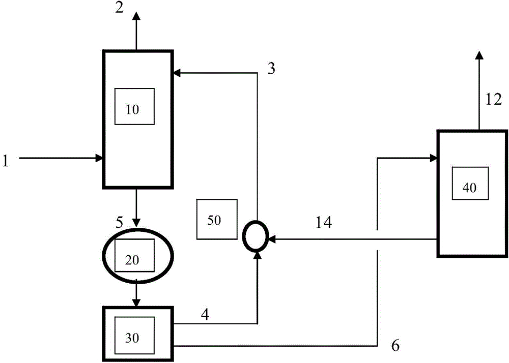
Deacidification process and system for gas mixtures containing acid gases
A technology of gas mixture and acid gas, which is applied in the field of deacidification process, to increase the absorption rate, reduce energy consumption, and reduce the overall effect
- Summary
- Abstract
- Description
- Claims
- Application Information
AI Technical Summary
Problems solved by technology
Method used
Image
Examples
Embodiment 1
[0099] The absorbent is composed of amine (Monoethanolamine (MEA)) with a volume ratio of 20% and water with a volume ratio of 80%. Under the condition of 25~45℃ and 1atm, the absorbent is contacted with the gas mixture containing acid gas (carbon dioxide) in the packed absorption tower. The absorbent absorbs acid gas to form a gas-rich (carbon dioxide) absorbent. Using a membrane separation method, the gas-rich absorbent flowing out of the packed tower is concentrated to form a concentrated amine phase. In the concentrated amine phase, all MEA (including untreated Chemically modified MEA and MEA and CO 2 The concentration of the reaction product) is about 80% by volume, and the water is 20%. The concentrated amine phase is separated from the remainder of the absorbent. After separation, the remainder of the absorbent contains most of the water with a small portion of MEA and absorbed CO 2 ,
[0100] The separated concentrated amine phase is transferred to a regenerator an...
Embodiment 2
[0102] This example demonstrates the absorption of CO by aqueous carbonate 2 .
[0103] An absorbent consisting of an aqueous carbonate solution. The absorbent is contacted with a gas mixture containing acid gas (carbon dioxide) in a packed absorption tower at 50°C and 1 atm. The absorbent absorbs acid gas to form a gas-rich (carbon dioxide) absorbent. Using a membrane separation method, the gas-rich absorbent flowing out of the packed tower is concentrated to form a concentrated carbonate phase. In the concentrated carbonate phase, all carbon salts (including unmodified carbonates as well as carbonates and CO 2 reaction product, bicarbonate). The concentrated carbonate phase is separated from the remainder of the absorbent. After separation, the remainder of the absorbent contains mostly water with minor portions of carbonates and bicarbonates.
[0104] The separated concentrated carbonate phase is transferred to a regenerator and treated by heating the concentrated carb...
Embodiment 3
[0106] The absorbent is composed of 30% by volume of amine (monoethanolamine or MEA+piperazine (a small amount)) and 70% by volume of solvent (isooctanol). The absorbent is contacted with a gas mixture containing acid gas (carbon dioxide) in a stirring cell absorption unit at 25-45°C and 1 atm. Monoethanolamine (MEA) within the absorbent condenses spontaneously into a concentrated amine phase containing MEA as well as MEA and CO 2 reaction product.
[0107] After absorption, the absorbent is settled by gravity to separate the concentrated amine phase from the rest of the absorbent. After separation, the remainder of the absorbent contains most of the isooctyl alcohol, perhaps some MEA and absorbed CO 2 , are recycled to the absorption unit for reuse. In the concentrated amine phase, all MEA (including unmodified MEA and MEA and CO 2 The concentration of the reaction product) is about 60-70% by volume.
[0108] The separated concentrated amine phase is transferred to a reg...
PUM
 Abstract
Description
Claims
Application Information
 - R&D
- Intellectual Property
- Life Sciences
- Materials
- Tech Scout
- Unparalleled Data Quality
- Higher Quality Content
- 60% Fewer Hallucinations
Browse by: Latest US Patents, China's latest patents, Technical Efficacy Thesaurus, Application Domain, Technology Topic, Popular Technical Reports.
© 2025 PatSnap. All rights reserved.Legal|Privacy policy|Modern Slavery Act Transparency Statement|Sitemap|About US| Contact US: help@patsnap.com

