Infrared vision sensing detection method and device for narrow-gap weld seam deviation

A technology of infrared vision sensing and welding seam deviation, which is applied in measuring devices, optical devices, welding equipment, etc., can solve the problems of low welding seam deviation sensing detection accuracy, narrow application range, and poor engineering practicability. Achieve the effect of improving weld deviation detection accuracy, improving real-time performance, and improving environmental adaptability

Active Publication Date: 2015-04-29
JIANGSU UNIV OF SCI & TECH
View PDF5 Cites 31 Cited by
  • Summary
  • Abstract
  • Description
  • Claims
  • Application Information

AI Technical Summary

Problems solved by technology

[0005] Aiming at the shortcomings of the existing technology such as low detection accuracy of weld deviation sensing, narrow application range, and poor engineering practicability, the present invention proposes a high detection accuracy, strong environmental adaptability, and good practicability, which is suitable for shaking (swinging) ), the infrared vision sensing detection method and device for the narrow gap weld deviation of the rotating arc, and obtain the weld deviation information by detecting the position change of the welding wire relative to the left and right side walls of the groove when the arc moves to the two sides of the groove

Method used


Image

  • Infrared vision sensing detection method and device for narrow-gap weld seam deviation
  • Infrared vision sensing detection method and device for narrow-gap weld seam deviation
  • Infrared vision sensing detection method and device for narrow-gap weld seam deviation

Examples


Embodiment 1

[0067] Example 1 (Take shaking arc DC welding as an example)

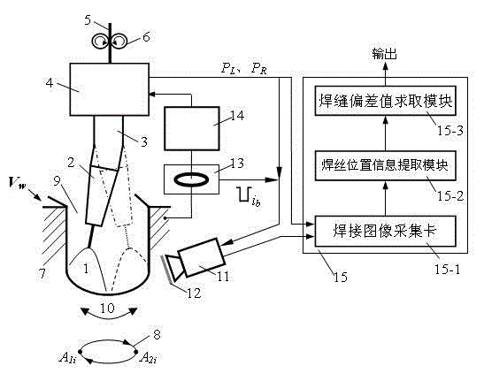
[0068] Picture 11 This is an example diagram of the extraction effect of the position information of the wire axis during DC welding. The test conditions include: the digital CMOS infrared camera 11 works in the external trigger mode, its camera angle is 25°, the aperture is 16, the exposure time is 2ms; the center wavelength of the narrow band filter is 970nm, the bandwidth is 25nm, and the transmittance of the neutral light-reducing film is 10 %; DC welding in flat position, arc current is 280A, arc voltage is 29V, welding speed is V w =20.3cm / min, the dry elongation of the welding wire is 18mm, the diameter of the welding wire is 1.2mm, the welding shielding gas Ar+20%CO 2 The flow rate is 30L / min, and the welding groove gap of type I low carbon steel is 13mm; Picture 11 At the corresponding moment, the welding torch is offset to the left (or the welding seam to the right) 0.5mm; the arc shaking frequency is 2.5Hz...

Embodiment 2

[0073] Example 2 (Take shaking arc pulse welding as an example)

[0074] Figure 13 This is an example diagram of the effect of extracting the position information of the wire axis during pulse welding. The test conditions include: the transmittance of the neutral dimmer sheet is 30%, the digital infrared CMOS camera works in the external trigger mode, the pulse MAG arc welding is adopted, and the average welding current Is 280A, the average arc voltage is 29V, the welding torch is offset to the right (or the weld is to the left) 0.6mm, and the other test conditions are the same as Picture 11 The conditions involved are the same.

[0075] When the arc swings closer to the side wall of the groove, the arc stays at the left side wall of the groove, signal P L Or stay signal P on the right side wall of the groove R Valid, once the arc current sensor 13 detects the first base value period current signal i of pulse arc 1 b When it comes, the infrared camera 11 is immediately triggered t...


PUM


Abstract

The invention discloses an infrared vision sensing detection method and an infrared vision sensing detection device for narrow-gap weld seam deviation. The device comprises a shaking (or rotating) electric arc narrow-gap welding torch, an electric arc current sensor, a computer image processing system and an infrared photographing system, wherein an infrared camera acquires an infrared image of a welding region in an external touch mode when an electric arm shakes (or rotates) to a position closest to the left side wall or the right side wall of a groove; after the infrared image is subjected to computer image processing, welding wire position and groove edge information is extracted in real time, and a weld seam deviation output is calculated according to changes of a welding wire relative to the left side wall and the right side wall of the groove; when a pulse electric arc is welded, the current sensor is used for detecting a signal in the base value period of electric arc current pulse, thus realizing welding image acquisition synchronized with the current period of a pulse electric arc base value. The system is simple in constitution, wide in application range, high in weld seam deviation detection precision, high in environment adaptability and high in interference capacity and is suitable for shaking (or swinging) and rotating electric arc narrow-gap welding occasions with groove width change.

Description

Technical field [0001] The invention relates to the technical field of welding, and particularly refers to an infrared vision sensing method and device for real-time detection of the deviation of a shaking (or swing) or rotating arc narrow gap weld. Background technique [0002] In the actual narrow-gap MIG welding process, it is often affected by factors such as groove processing error, workpiece assembly error, welding thermal deformation, etc., resulting in changes in the size of the groove gap and the center position of the weld, and the torch center deviates from the welding. The center of the seam (that is, the occurrence of weld deviation). If the welding seam is not tracked and controlled, the welding seam deviation will accumulate, so even if the groove sidewall penetration control technology based on arc swing or rotation technology is adopted, it will affect the quality of narrow gap welding. Sensing technology is the key to realizing seam tracking. Weld seam tracking...

Claims


Application Information

Patent Timeline
Patent Type & Authority Applications(China)
IPC IPC(8): B23K9/127B23K9/09B23K9/022B23K9/173
CPCB23K9/022B23K9/09B23K9/1274B23K9/173B23K9/0213B23K9/0216B23K9/0956G06T2207/30152G06T7/73G06T7/0004G06T2207/10048G06T2207/30136G06T7/136G06T7/13G06T7/155B23K31/125G01B11/022G01B11/14G01R19/0092G06T2207/20032G06T2207/20036
Inventor 王加友朱杰张才杨茂森苏娜黎文航
Owner JIANGSU UNIV OF SCI & TECH
Why Eureka
Try Eureka