Pyrolysis system and pyrolyzing method
A pyrolysis and pyrolysis furnace technology, applied in the pyrolysis system and the field of pyrolysis, can solve problems that are rarely mentioned, and achieve the effects of improving the uniformity of heating, improving the efficiency and degree of pyrolysis, and increasing the contact area.
- Summary
- Abstract
- Description
- Claims
- Application Information
AI Technical Summary
Problems solved by technology
Method used
Image
Examples
Embodiment 1
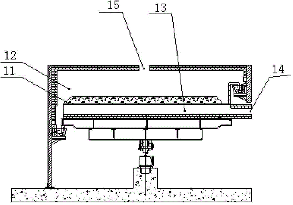
[0077] Coal samples with a particle size of 5 mm to 30 mm (see Table 1 for coal quality analysis data) are continuously fed into the rotary bed pyrolysis furnace at a rate of 3 t / h, and are directly contacted with non-condensable gas at a temperature of about 580 ° C to exchange heat and generate heat. Solution, heating the coal block to 530°C to generate hot semi-coke, tar steam and gas, the obtained hot semi-coke at a temperature of about 500°C enters the cooling system for cooling to recover heat, and the cooled semi-coke is sent to the storage bin. The temperature of the generated oil gas mixed with the heating non-condensable gas is about 520°C, and it is led out of the rotary bed pyrolysis furnace through multiple oil and gas outlets on the top of the rotary bed pyrolysis furnace. The oil and gas outlet positions are different, and the outlet oil gas temperature has a certain difference. The oil and gas from each oil and gas outlet are combined through the oil and gas mai...
Embodiment 2
[0083] The coal sample used in this example with a raw coal particle size of 5 mm to 30 mm is continuously fed into the rotary bed pyrolysis furnace at 2.6 t / h, and is in direct contact with non-condensable gas at a temperature of about 650 ° C to exchange heat and generate heat. Solution, heating the coal block to 600°C to generate hot semi-coke, tar steam and gas, the obtained hot semi-coke is about 580°C and enters the cooling system for cooling to recover heat, and the cooled semi-coke is sent to the storage bin. The temperature of the generated oil gas mixed with the heating non-condensable gas is about 590°C, and it is led out of the rotary bed pyrolysis furnace through multiple oil and gas outlets on the top of the rotary bed pyrolysis furnace. The oil and gas outlet positions are different, and the outlet oil gas temperature has a certain difference. The oil and gas from each oil and gas outlet are combined through the oil and gas main pipe and then enter the cooling an...
Embodiment 3
[0087] Autumn domestic garbage in a certain area with a particle size of 5 mm to 120 mm is continuously fed into the rotating bed at a rate of 1.3 t / h, directly contacts with non-condensable gas at a temperature of about 800 °C for heat exchange, and pyrolyzes at 700 °C to generate thermal solids Carbon-containing matter, tar vapor and combustible gas, the temperature of the obtained hot solid carbon-containing matter is about 680°C, enters the cooling system to cool and recover heat, and the cooled solid carbon-containing matter is sent to the storage bin. The mixture of oil gas and heating non-condensable gas is drawn out of the rotating bed through multiple oil and gas outlets on the top of the rotating bed. The temperature of the high-temperature oil and gas mixed with the non-condensable gas is 690°C, and the oil and gas from each oil and gas outlet are combined into cooling through the oil and gas main pipe. and purification system.
[0088] The moisture content of domes...
PUM
 Abstract
Description
Claims
Application Information
 - Generate Ideas
- Intellectual Property
- Life Sciences
- Materials
- Tech Scout
- Unparalleled Data Quality
- Higher Quality Content
- 60% Fewer Hallucinations
Browse by: Latest US Patents, China's latest patents, Technical Efficacy Thesaurus, Application Domain, Technology Topic, Popular Technical Reports.
© 2025 PatSnap. All rights reserved.Legal|Privacy policy|Modern Slavery Act Transparency Statement|Sitemap|About US| Contact US: help@patsnap.com


