An argon filling and stabilizing device

A steady flow device and argon gas technology, which is applied in the directions of crystal growth, single crystal growth, polycrystalline material growth, etc., can solve the problems of large bias current, excessive oxygen and carbon content of the crystal rod, etc., achieve simple structure, improve crystal quality, The effect of strong reliability

Active Publication Date: 2017-03-29
MCL ELECTRONICS MATERIALS
View PDF10 Cites 0 Cited by
  • Summary
  • Abstract
  • Description
  • Claims
  • Application Information

AI Technical Summary

Problems solved by technology

The disclosed argon filling and stabilizing device ensures sufficient flow of argon through rational design of the argon filling pores and gas path, and meets the pressure requirements of the silicon single crystal pulling process on the inside of the furnace body; it adopts multiple split flow of the pre-stage rectifier The structural design and the structural design of the post-stage steady flow from narrow neck to enlarged diameter solve the problem of large bias flow of argon gas entering the single crystal furnace chamber, making the flow of argon gas after entering the furnace chamber stable and orderly, eliminating the flow vortex and cause The swing of the growing crystal rod caused by the impact of the airflow
The diversion groove structure design with expanded diameter and stable flow makes the argon gas distribution even in the furnace chamber, and the entire furnace chamber can be evenly filled with inert gas to solve the problem of excessive oxygen and carbon content in the ingot

Method used


Image

  • An argon filling and stabilizing device
  • An argon filling and stabilizing device
  • An argon filling and stabilizing device

Examples


specific Embodiment approach

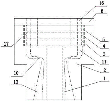
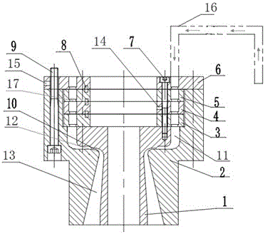
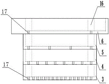
[0011] Provide the specific embodiment of the present invention below in conjunction with accompanying drawing as follows:

[0012] like figure 1 , figure 2 , image 3 As shown, a kind of argon gas filling and stabilizing device according to the present invention is mainly composed of a front-stage rectifier, a rear-stage stabilizing fluid, a stabilizing fluid diversion groove 11, a top-down inner hexagonal connecting screw 7, a positioning Bearing pin 8, inner hexagonal connecting screw 9 form from bottom to top. Among them, the pre-stage rectifier is composed of the primary distribution layer 6, the secondary distribution layer 5, the third distribution layer 4, and the final distribution layer 3. The primary distribution layer 6, the secondary distribution layer 5, the third distribution layer 4 and the final Air distribution holes 17 are respectively provided on the distribution layer 3 to form a four-stage air distribution flow multiplied step by step. The gas distri...


PUM

PropertyMeasurementUnit
heightaaaaaaaaaa
sizeaaaaaaaaaa
sizeaaaaaaaaaa

Abstract

The invention discloses an argon-filling flow stabilization device applied to filling argon in a single crystal furnace in the Czochralski method silicon single crystal production process. According to the argon filled flow stabilization device disclosed by the invention, due to the combined action of a forward stage stabilization body and a backward stage stabilization body of four-level air distribution hole flow in step-by-step multiplication of a primary shunt layer (6), a secondary shunt layer (5), a third-level shunt layer (4) and a tail-level shunt layer (3) as well as a stabilization body guide groove (11), the flow of the argon filled into the single crystal furnace is stably and orderly distributed, the bias flow is small, the argon distribution in the furnace chamber is uniform, the problems that a crystal bar swings and the oxygen and carbon content of the crystal bar exceeds the standard due to argon filling are effectively solved, and the crystal formation rate is obviously improved. The argon-filling flow stabilization device disclosed by the invention is simple in design structure, reliable to assemble and position and convenient to mount and maintain.

Description

technical field [0001] The invention belongs to the technical field of Czochralski silicon single crystal production, and mainly relates to an argon filling and stabilizing device. Background technique [0002] During the silicon single crystal production process, the gas filling system on the single crystal furnace is responsible for filling the inside of the single crystal furnace with argon gas, and the argon gas flow runs through the single crystal production area from top to bottom, so that the single crystal in production is always inert In the gas environment, and ensure the stability of the pressure inside the single crystal furnace chamber. At the same time, the argon gas flow can carry the silicon oxide and impurity volatiles produced by the high temperature in the furnace chamber, and take them out of the furnace chamber through the vacuum system of the single crystal furnace. However, in the process of argon gas filling, there are problems of uneven distribution...

Claims


Application Information

Patent Timeline
Patent Type & Authority Patents(China)
IPC IPC(8): C30B15/00C30B29/06
Inventor 韩子萌司鹏辉
Owner MCL ELECTRONICS MATERIALS
Why Eureka
Try Eureka