A method and device for flattening scattering traces of a distributed optical fiber sensing system

A technology of distributed optical fiber and flattening method, applied in the direction of using optical devices to transmit sensing components, general control systems, control/adjustment systems, etc., can solve the problem of increasing construction difficulty and construction cost, reducing the performance and stability of optical cables, increasing Optical signal loss and other problems, to achieve the effect of eliminating blind spots of sensing, good real-time performance, and improving spatial dynamic range

Active Publication Date: 2017-02-22
SOUTHEAST UNIV
View PDF6 Cites 0 Cited by
  • Summary
  • Abstract
  • Description
  • Claims
  • Application Information

AI Technical Summary

Problems solved by technology

Although this method can eliminate the sensing blind area of ​​the system, under normal circumstances, a redundant optical fiber, two optical fiber fusion points and an optical fiber splicing box need to be added to a blind area, which increases the loss of optical signals and increases the difficulty of construction. cost, reduces the performance and stability of the entire fiber optic cable
The disadvantage of this method is more obvious if the system has multiple sensing dead zones

Method used


Image

  • A method and device for flattening scattering traces of a distributed optical fiber sensing system
  • A method and device for flattening scattering traces of a distributed optical fiber sensing system
  • A method and device for flattening scattering traces of a distributed optical fiber sensing system

Examples


Embodiment 1

[0072] A method for flattening scattered traces of a distributed optical fiber sensing system, comprising the following steps:

[0073] 1) The synchronous signal generation module 1 continuously generates trigger signals and transmits them to the light source drive module 2 and the analog-to-digital converter 5 at the same time, continuously generates delay control signals and sends them to the discrete digital delayer 6, and the cycle of the trigger signals is T, after the light source driving module 2 receives the trigger signal, it generates an electric pulse signal with a width of τ, and the phase of the electric pulse signal is the same as that of the trigger signal, and then outputs the electric pulse signal to A light source 3, which generates an optical pulse signal with a width τ and transmits it to the optical fiber optical path, and the phase of the optical pulse signal is the same as that of the electrical pulse signal;

[0074] 2) After the optical fiber optical p...

Embodiment 2

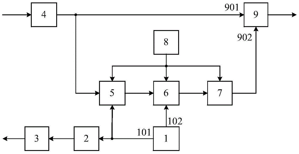
[0117] A distributed optical fiber sensing system scattering trace flattening device, including a synchronous signal generation module 1, a light source drive module 2, a light source 3, a photodetector 4, an analog-to-digital converter 5, a discrete digital delayer 6, a digital Analog converter 7, clock signal generation module 8 and subtractor 9;

[0118] The trigger signal output interface 101 of the synchronous signal generating module 1 is connected to the control interface of the light source driving module 2 and the control interface of the analog-to-digital converter 5 at the same time, and the control signal output interface 102 of the synchronous signal generating module 1 is connected to the discrete digital The control interface of the delayer 6 is connected, the output interface of the light source driving module 2 is connected with the control interface of the light source 3; the output interface of the photodetector 4 is simultaneously connected with the signal i...

Embodiment 3

[0152] In this implementation case, the distributed optical fiber sensing system is a distributed optical fiber vibration sensing system, the length L of the optical fiber optical path is 19 km, the period T of the trigger signal output by the synchronization signal generating module 1 is 190 μs, and the output of the light source driving module 2 is The electrical pulse width and the optical pulse width τ output by the light source 3 are 1 μs, the sampling period S of the analog-to-digital converter 5 is 20 ns, the sampling length Z in a trigger signal period T is 9500, and the delay of the discrete digital delayer 6 When the number of cycles N is 1, the delay time D is 190μs. Disturbance is applied at the optical fiber optical path length of 9km, and the frequency of the disturbance signal is 1000Hz. Figure 21 The backscattered electrical signal V(t) output by the photodetector 4 and the flattened backscattered electrical signal Y(t) output by the subtractor 9 are given in ...


PUM


Abstract

The invention discloses a method and device for leveling a scattering path line of a distributed fiber-optic sensing system. The device comprises a synchronizing signal generating module, a photodetector and a clock signal generating module, wherein a signal output interface of the synchronizing signal generating module is connected with a control interface of a light source driving module and a control interface of a modulus converter, and a control interface of the synchronizing signal generating module is connected to a control interface of a discrete type digital delayer; the light source driving module is connected to a light source; an output interface of the photodetector is connected with a signal input interface of the modulus converter and a minuend input interface of a subtracter, and an output interface of the modulus converter is sequentially connected with the discrete type digital delayer, a digital-analog converter and the minuend input interface of the subtracter; the clock signal generating module provides a clock for the modulus converter, the discrete type digital delayer and the digital-analog converter; the output of the light source, the input of the photodetector and the output of the subtracter are respectively used as a light output interface, a light input interface and a signal output interface of the whole device.

Description

technical field [0001] The invention belongs to the field of distributed optical fiber sensing and signal processing, and relates to a method and device for flattening scattering traces of a distributed optical fiber sensing system. Background technique [0002] Distributed optical fiber sensing technology is a new type of sensing technology that uses light waves as the carrier and optical fiber as the medium to sense the measured physical quantities outside the sensing optical fiber. It has long-distance continuous sensing, low loss, small size, radiation resistance, corrosion resistance, etc. Many advantages have been widely concerned. The use of optical fiber backscattering mechanism is an important means to realize long-distance distributed optical fiber sensing. However, the climate and construction environment of the project site are complex and changeable, and the conditions of the sensing optical cable are harsh, which brings great challenges to the signal processin...

Claims


Application Information

Patent Timeline
Patent Type & Authority Patents(China)
IPC IPC(8): G01D5/353G05B19/042
Inventor 孙小菡叶红亮潘超李明铭赵澍慧
Owner SOUTHEAST UNIV
Why Eureka
Try Eureka