
Waste treatment method and waste incinerator

A treatment method and waste technology, applied in the direction of incinerators, combustion methods, combustion types, etc., can solve the problem of expensive catalysts and achieve the effect of inhibiting the reaction of NOx formation

Active Publication Date: 2017-12-05
EBARA ENVIRONMENTAL PLANT
View PDF3 Cites 0 Cited by
  • Summary
  • Abstract
  • Description
  • Claims
  • Application Information

AI Technical Summary

Problems solved by technology

[0008] In the past, it has been used to blow ammonia into the exhaust gas discharged from the incinerator, and selectively combine ammonia and NO with a catalyst. x Catalyst denitrification method that reacts and decomposes into water and nitrogen. However, since the catalyst is expensive, it is also used to blow ammonia into the exhaust gas and remove NO without using a catalyst. x Decomposition Catalyst-free Denitrification

Method used


Image

  • Waste treatment method and waste incinerator
  • Waste treatment method and waste incinerator
  • Waste treatment method and waste incinerator

Examples


Embodiment Construction

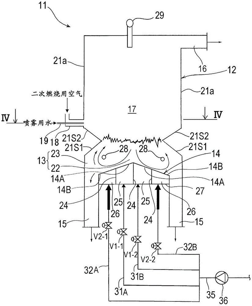
[0080] Below, refer to Figure 1 to Figure 15 Embodiments of the waste treatment method and the waste incinerator of the present invention will be described. exist Figure 1 to Figure 15 In , the same reference numerals are assigned to the same or equivalent constituent elements, and overlapping descriptions are omitted.

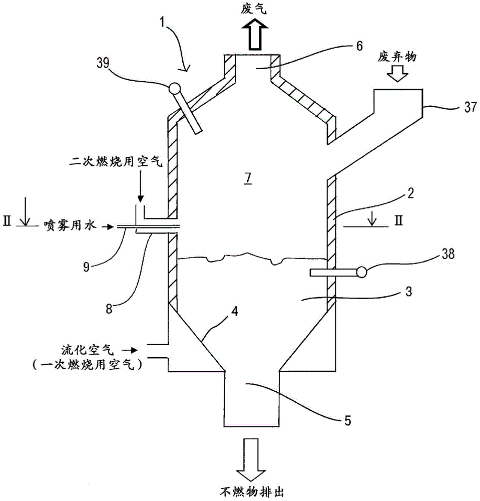
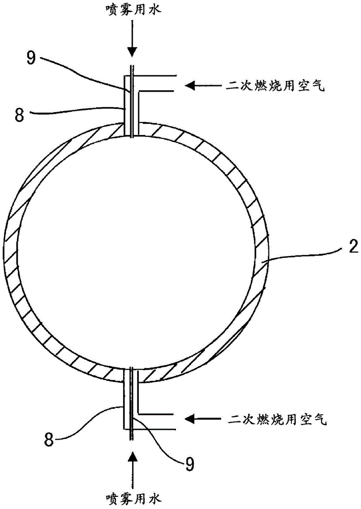
[0081] figure 1 It is a longitudinal sectional view showing a fluidized bed incinerator which is an embodiment of the waste incinerator of the present invention. figure 2 yes figure 1 Ⅱ-Ⅱ line sectional view. Such as figure 1 and figure 2 As shown, a fluidized bed incinerator 1 has a furnace body 2 for processing waste, a fluidized bed 3 for pyrolyzing and partially burning introduced waste, and a bed plate 4 for supporting the fluidized bed 3 . The fluidized bed 3 is typically a sand layer formed by accumulating sand such as silica sand, that is, a fluidizing medium. The space above the fluidized bed 3 inside the furnace body 2 becomes a free s...


PUM


Abstract

The present invention relates to a method for treating wastes and a waste incinerator, and more particularly to a method for treating wastes and a waste incinerator for performing incineration treatment of wastes such as municipal wastes, shredder dust, and waste plastics. In the method for treating wastes by incinerating the wastes with an incinerator (1), the method for treating wastes includes combusting part of wastes at a primary air ratio ranging from 0.3 to 0.8 to generate a combustible gas, and supplying secondary combustion air to the generated combustible gas and spraying water in the generated combustible gas to perform secondary combustion of the combustible gas in the presence of water.

Description

technical field [0001] The invention relates to a waste treatment method and a waste incinerator, in particular to a waste treatment method and a waste incinerator for incinerating waste such as municipal garbage, shredder debris, and waste plastics. Background technique [0002] In order to efficiently and hygienically compress municipal waste, shredder debris, waste plastics and other wastes, waste has always been incinerated through incinerators. Nitrogen oxides (NO x ), so the exhaust gas from the incinerator contains a large amount of NO x . About NO x The reason for the generation is because of the oxidation of nitrogen compounds in the incineration (fuel type NO x (Fuel-NO x )) and oxidation of nitrogen in air (thermal NO x (Thermal-NO x )), but in waste incinerators it can be said that fuel type NO x (Fuel-NO x ) is the subject. [0003] To reduce NO emitted from waste incinerators x For example, Non-Patent Document 1 discloses a measure for reducing nitro...

Claims


Application Information

Patent Timeline
Patent Type & Authority Patents(China)
IPC IPC(8): F23G5/027F23C10/18F23C99/00F23G5/00F23G5/14F23G5/16F23G5/20F23G5/30F23G5/44F23G5/50F23L7/00
CPCF23C10/18F23C99/00F23G5/027F23G5/16F23G5/20F23G5/30F23G5/44F23G5/50F23L7/007F23G5/14F23L7/00Y02E20/12Y02E20/34
Inventor 石川龙一山口繁吉良诚中村幸弘今村浩喜池田太菊地孝辅佐藤隆英
Owner EBARA ENVIRONMENTAL PLANT
Learn More