Hybrid capacitor and manufacturing method thereof
A technology for hybrid capacitors and supercapacitors, applied in hybrid capacitor electrodes, hybrid/electric double-layer capacitor manufacturing, multiple hybrid/electric double-layer capacitors, etc., can solve the problem of large equivalent series resistance, limited application, and poor frequency characteristics and other problems, to achieve the effect of low equivalent series resistance, large capacity, and excellent frequency characteristics
- Summary
- Abstract
- Description
- Claims
- Application Information
AI Technical Summary
Problems solved by technology
Method used
Image
Examples
preparation example Construction
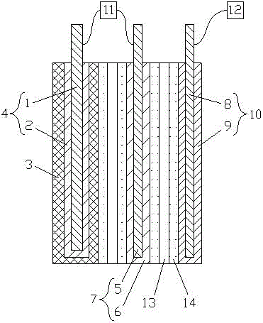
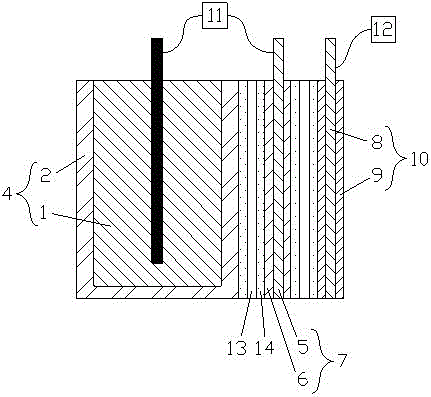
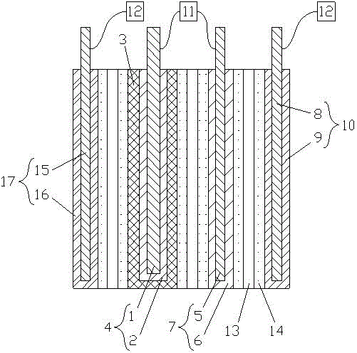
[0037] (1) Preparation of positive plate 4 of electrolytic capacitor: cover a layer of oxide of corresponding valve metal or oxide 2 of niobium monoxide on the surface of valve metal or niobium monoxide 1 to make positive plate 4 of electrolytic capacitor;
[0038] (2) Preparation of supercapacitor positive electrode sheet 7: Cover at least one layer of positive electrode active layer 6 containing positive electrode active material on the surface of supercapacitor positive electrode current collector 5 to make supercapacitor positive electrode sheet 7, and the supercapacitor positive electrode sheet 7 is combined with electrolytic There is no direct contact between the oxides of the valve metal or the oxides 2 of niobium monoxide on the positive electrode sheet 4 of the capacitor;
[0039] (3) Connection of the positive electrode 11: connect the valve metal or niobium monoxide 1 of the positive electrode of the electrolytic capacitor and the positive current collector 5 of the ...
Embodiment 1
[0049] Example 1: Such as figure 1 As shown, wherein, the valve metal 1 of the positive plate of the electrolytic capacitor is corroded aluminum foil, and the valve metal oxide 2 covered on the surface is aluminum oxide, which is made into the positive plate 4 of the electrolytic capacitor, and the surface is also covered with conductive polyethylenedioxythiophene The solid conductive layer 3 of the supercapacitor positive electrode sheet 7 is an aluminum foil, and the surface is covered with a positive electrode active layer 6 containing activated carbon, which is made into a supercapacitor positive electrode sheet 7; the supercapacitor positive electrode sheet 7 and the surface are covered with a solid conductive layer 3 The positive electrode sheets 4 of the electrolytic capacitor are overlapped, but a diaphragm 13 is arranged between them, and the valve metal 1 of the positive electrode sheet 4 of the electrolytic capacitor and the positive current collector 5 of the posi...
Embodiment 2
[0051] Example 2: Such as figure 2 As shown, wherein, the valve metal 1 of the positive plate of the electrolytic capacitor is a sintered tantalum block, and the valve metal oxide 2 covered on the surface is tantalum pentoxide, which is made into the positive plate 4 of the electrolytic capacitor; the positive current collector 5 of the positive plate 7 of the supercapacitor It is a tantalum foil, the surface is covered with a positive electrode active layer 6 containing activated carbon, and it is made into a positive electrode sheet 7 of a super capacitor; The valve metal 1 and the positive current collector 5 of the positive plate 7 of the supercapacitor are respectively connected to the positive electrode 11 . Wherein, the negative electrode current collector 8 of the supercapacitor negative electrode sheet 10 is a tantalum foil, and the surface is covered with a negative electrode active layer 9 containing activated carbon to make a supercapacitor negative electrode sh...
PUM
 Abstract
Description
Claims
Application Information
 - R&D
- Intellectual Property
- Life Sciences
- Materials
- Tech Scout
- Unparalleled Data Quality
- Higher Quality Content
- 60% Fewer Hallucinations
Browse by: Latest US Patents, China's latest patents, Technical Efficacy Thesaurus, Application Domain, Technology Topic, Popular Technical Reports.
© 2025 PatSnap. All rights reserved.Legal|Privacy policy|Modern Slavery Act Transparency Statement|Sitemap|About US| Contact US: help@patsnap.com


