Reactor and process for preparing hydrogen sulphide

A technology of reactors and hydrogen sulfide, applied in chemical instruments and methods, hydrogen sulfide, chemical methods for reacting liquid and gaseous media, etc., can solve a large number of problems

Inactive Publication Date: 2015-05-06
EVONIK OPERATIONS GMBH
View PDF13 Cites 4 Cited by
  • Summary
  • Abstract
  • Description
  • Claims
  • Application Information

AI Technical Summary

Problems solved by technology

However, it has been found that these reactors have the disadvantage that they operate at a pressure of less than 5 bar and that, due to the fact that the reaction of sulfur and hydrogen is mainly catalytic, large amounts of catalyst are required

Method used


Image

  • Reactor and process for preparing hydrogen sulphide
  • Reactor and process for preparing hydrogen sulphide
  • Reactor and process for preparing hydrogen sulphide

Examples


Embodiment 1

[0106] Embodiment 1 (comparative example)

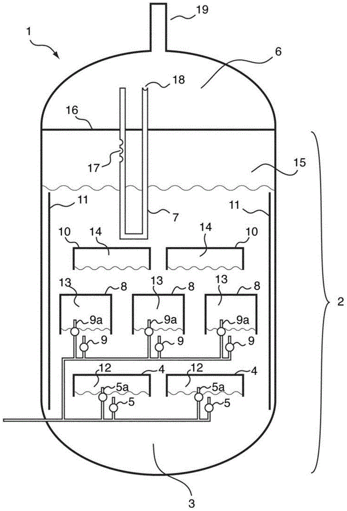
[0107] 1000 l(STP) / h of hydrogen were introduced continuously via a glass frit at the base into a tube with an inner diameter of 5 cm which had been filled with liquid sulfur up to a height of 1 m. The sulfur consumed is compensated by further metering in liquid sulfur while keeping the filling level constant. Sulfur removed from the product gas stream by condensation is recycled in liquid form into the upper region of the tube. Above the liquid sulfur, sheathed thermocouples for measuring temperature were placed at intervals of 10 cm. When the reactor was electrically heated to 400°C via the outer wall, there was a uniform temperature of about 397°C within the sulfur. However, the thermocouple located above the sulfur showed the highest temperature of 520 °C. In addition, above the liquid sulfur, a sample of the new material made of standard stainless steel (1.4571) was provided at the position of the highest temperature. After ...

Embodiment 2

[0108] Embodiment 2 (comparative example)

[0109] Example 1 was repeated, except that the height of the liquid sulfur was raised to 4m. Maintain the highest temperature value above the liquid sulfur. Severe corrosion phenomena also occurred on material samples.

Embodiment 3

[0110] Embodiment 3 (comparative example)

[0111] Repeat Example 2, except that 15% by weight of powdered Co 3 o 4 MoO 3 / Al 2 o 3 The catalyst is suspended in liquid sulfur. Maintain the highest temperature value above the liquid sulfur. Severe corrosion phenomena also occurred on material samples.


PUM

PropertyMeasurementUnit
heightaaaaaaaaaa
diameteraaaaaaaaaa
porosityaaaaaaaaaa

Abstract

The reactor comprises: a lower reactor region (2) for accommodating a sulfur melt (3); non-pressure-bearing first caverns (4) for temporary accommodation of a product gas mixture that is formed by exothermic reaction and comprises hydrogen sulfide, sulfur and hydrogen; non-pressure bearing second caverns (8) arranged above the first caverns and for temporary accommodation of the product gas mixture formed in the first caverns and for formation of further hydrogen sulfide by exothermic reaction of sulfur and hydrogen to form a product gas mixture; and a gas collecting region (6). The reactor comprises: a lower reactor region (2) for accommodating a sulfur melt (3); non-pressure-bearing first caverns (4) for temporary accommodation of a product gas mixture that is formed by exothermic reaction and comprises hydrogen sulfide, sulfur and hydrogen, and a supply device for controlled supply of pressurized gaseous hydrogen per first cavern; non-pressure bearing second caverns (8) arranged above the first caverns and suitable for temporary accommodation of the product gas mixture formed in the first caverns and for formation of further hydrogen sulfide by exothermic reaction of sulfur and hydrogen to form a product gas mixture; and a gas collecting region (6) for accommodating the product gas mixture at elevated temperature and elevated pressure relative to standard conditions. One of the second caverns comprises a supply device suitable for controlled supply of pressurized gaseous hydrogen. The reactor further comprises: non-pressure-bearing third caverns arranged above the second caverns; non-pressure-bearing installed devices suitable for continuous transfer of a total amount of product gas mixture formed in the lower reactor region to the gas collecting region, where a catalyst is present in the installed devices suitable for reacting sulfur and hydrogen still present in the product gas mixture to form hydrogen sulfide; an inner wall that allows continuous circulation of the sulfur melt according to an airlift pump principle in the course of operation of the reactor with involvement of a space between an outer reactor wall and the inner wall; a reflux condenser suitable for condensation of the sulfur present in the product gas mixture; and an input line suitable for transport of the product gas mixture from the gas collecting region to the reflux condenser and a return line suitable for return of the condensed sulfur to the reactor. One of the second or third caverns has a greater volume than each of the first caverns, and / or one of the second or third caverns has lower heat removal for construction reasons than each of the first caverns. The installed devices are arranged such that, the installed devices are present in thermal contact with the sulfur melt after sufficient filling of the lower reactor region with the sulfur melt. The catalyst is cooled by transfer of heat to the sulfur melt if the installed devices contain the catalyst. An independent claim is included for a process for preparing hydrogen sulfide by exothermic reaction of sulfur with hydrogen at elevated temperature and elevated pressure relative to standard conditions to form a product gas mixture comprising hydrogen sulfide and sulfur.

Description

technical field [0001] The present invention relates to a reactor and process for the synthesis of hydrogen sulfide from elemental sulfur and hydrogen at elevated pressure and elevated temperature. The present invention also relates to the use of said reactors for high yield and low H 2 S x content for the preparation of hydrogen sulfide. Background technique [0002] Hydrogen sulfide is an industrially important intermediate, e.g. for the synthesis of methyl mercaptan, dimethyl sulfide, dimethyl disulfide, sulfonic acid, dimethyl sulfoxide, dimethyl sulfone, and for many sulfur reaction. To date, it has been obtained mainly from mineral oil and natural gas processing and by the reaction of sulfur and hydrogen. [0003] Hydrogen sulfide is usually produced from elemental substances by introducing gaseous hydrogen into a sulfur melt, converting the sulfur into the gas phase and converting the sulfur therein to hydrogen sulfide in an exothermic reaction with hydrogen (Ullm...

Claims


Application Information

Patent Timeline
Patent Type & Authority Applications(China)
IPC IPC(8): C01B17/16B01J8/06B01J10/00B01J19/00B01J19/24B01J4/00
CPCC01B17/162B01J4/002B01J8/067B01J10/005B01J19/006B01J19/24B01J2219/00166B01J2219/00768B01J2219/00777B01J7/02B01J19/2415C01B17/20B01J2219/24
Inventor C·H·芬克尔代C·K·张R·马森S·文纳M·克费尔
Owner EVONIK OPERATIONS GMBH
Why Eureka
Try Eureka