
Axisymmetric comb-shaped inner fin structure and fin tube thereof

An inner fin and axisymmetric technology, which is applied in the engineering application field of heat transfer, can solve the problem of not being able to realize the uniform maximization of the temperature in the heat transfer process of the flow cross section, not being able to obtain the cooling of the fin's low-temperature surface, and destroying the radial distribution mode of the airflow temperature and other issues, to achieve the effect of improving product competitiveness, simple structure, and convenient processing and production

Inactive Publication Date: 2015-05-13
XI AN JIAOTONG UNIV
View PDF8 Cites 5 Cited by
  • Summary
  • Abstract
  • Description
  • Claims
  • Application Information

AI Technical Summary

Problems solved by technology

[0005] 1. Although the center-symmetric equal-height fins can destroy the fluid boundary layer near the wall to a certain extent, they cannot play a role in the central fluid, and the central flow field has not been effectively destroyed, and the low degree of turbulence also limits convection Improvement of heat transfer coefficient
[0006] 2. The radial distribution pattern of the airflow temperature cannot be completely destroyed, the center of the airflow cannot be cooled by the low-temperature surface of the fins, and there are still local high-temperature airflow areas, which cannot maximize the temperature uniformity in the heat transfer process of the flow cross-section

Method used


Image

  • Axisymmetric comb-shaped inner fin structure and fin tube thereof
  • Axisymmetric comb-shaped inner fin structure and fin tube thereof
  • Axisymmetric comb-shaped inner fin structure and fin tube thereof

Examples


Embodiment Construction

[0033] The present invention will be described in more detail below in conjunction with the accompanying drawings.

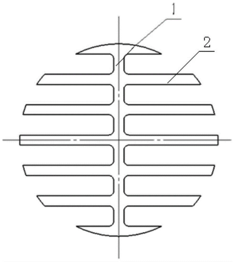
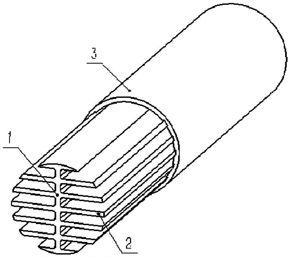
[0034] Such as figure 1 As shown, the present invention is an axisymmetric comb-shaped inner fin structure, which is composed of a central rib 1 and a plurality of sets of inner fin pairs vertically arranged on the central rib 1 integrally formed with the central rib 1, and each set of inner fins The pair consists of two inner fins 2 distributed axially symmetrically along the central rib 1 .

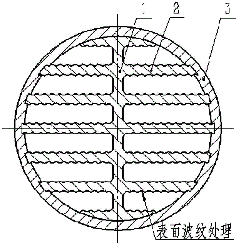
[0035] As a preferred embodiment of the present invention, the surface of the inner fin 2 is longitudinally corrugated, and the corrugation form is a zigzag, rectangular or sinusoidal function waveform, so that the overall heat transfer area is further increased on the original, and greatly enhanced The fluid disturbance is reduced, and the heat and mass transfer effect is improved. Such as image 3 Shown is a schematic cross-sectional view of the surface of the inner ...


PUM


Abstract

The invention discloses an axisymmetric comb-shaped inner fin structure and a fin tube thereof. The inner fined structure comprises a centre rib, and a plurality of inner fin pairs. The plurality of inner fin pairs are arranged on the centre rib vertically and integrated forming with the centre rib. One inner fin pair comprises two inner fins, and the two inner fins are arranged in an axial symmetry mode along the centre rib. The fine tube comprises the axisymmetric comb-shaped inner fin structure and an outer tube arranged out of the axisymmetric comb-shaped inner fin structure. The inner wall shape of the outer tube are matched with with the external shape of the axisymmetric comb-shaped inner fin structure. The outer tuber is in interference fit with the axisymmetric comb-shaped inner fin structure. The axisymmetric comb-shaped inner fin structure and a fin tube thereof have the advantages that the high-temperature gas is divided into a plurality of heat transfer zones, a radial distribution gas temperature gradient mode in a traditional heat exchanger element is changed effectively, a heat transfer effect of the inertia heat transfer zone in the traditional heat exchanger element center is improved, and the maximization of the uniformity of the cross-section temperature field is achieved.

Description

technical field [0001] The invention belongs to the technical field of engineering application of heat transfer, and in particular relates to an axisymmetric comb-tooth-shaped inner fin structure and a fin tube bundle thereof. Background technique [0002] The shell-type structure of industrial boilers and tube-type air preheaters and waste heat boilers in chemical processes widely use smoke tubes as heat exchange tube bundles, that is, flue gases from boiler combustion or chemical processes flow through the tubes for convective heat exchange, transferring heat The working medium water on the outside of the tube is supplied to realize heat energy conversion. [0003] We know that when the flue gas flows longitudinally in the pipe, the heat transfer coefficient between the flue gas and the pipe wall is small, and the flue gas in the center of the pipe cannot contact the metal on the inner wall of the pipe, and it takes a long tube bundle to reduce the temperature of the smoke...

Claims


Application Information

Patent Timeline
Patent Type & Authority Applications(China)
IPC IPC(8): F28F1/40
Inventor 赵钦新焦健陈中亚孙一睿潘佩媛杨文君
Owner XI AN JIAOTONG UNIV
Learn More