
Multi-beam scanning lens antenna

A scanning lens and multi-beam technology, applied in the direction of antennas, antenna arrays, antenna grounding devices, etc., can solve the problems of complex structure, high cost, limited scanning range, etc., and achieve the effect of small occupied volume, good reflection effect and low cost

Inactive Publication Date: 2015-05-13
NORTHWESTERN POLYTECHNICAL UNIV
View PDF2 Cites 20 Cited by
  • Summary
  • Abstract
  • Description
  • Claims
  • Application Information

AI Technical Summary

Problems solved by technology

[0003] Traditional multi-beam antennas include reflector antennas and phased array antennas. The disadvantages of these antennas are complex structures, limited scanning range, large loss, narrow operating frequency band, etc., while multi-beam lens antennas have good symmetry and retain Good optical characteristics, and there is no obstruction to the feed source within a certain range, which can realize scanning in a wide range of angles and work with low loss
[0004] Most of the current multi-beam lens antennas are fed by waveguide horns. The shape of the lens is mostly spherical or hemispherical, which can realize multi-directional beam scanning. Large, not easy to bend, not conducive to the integration of lens antenna systems, and the ball lens with gradual dielectric constant is difficult to process, high in cost, and not easy to fix, which limits the application of lens antennas

Method used


Image

  • Multi-beam scanning lens antenna
  • Multi-beam scanning lens antenna
  • Multi-beam scanning lens antenna

Examples


Embodiment

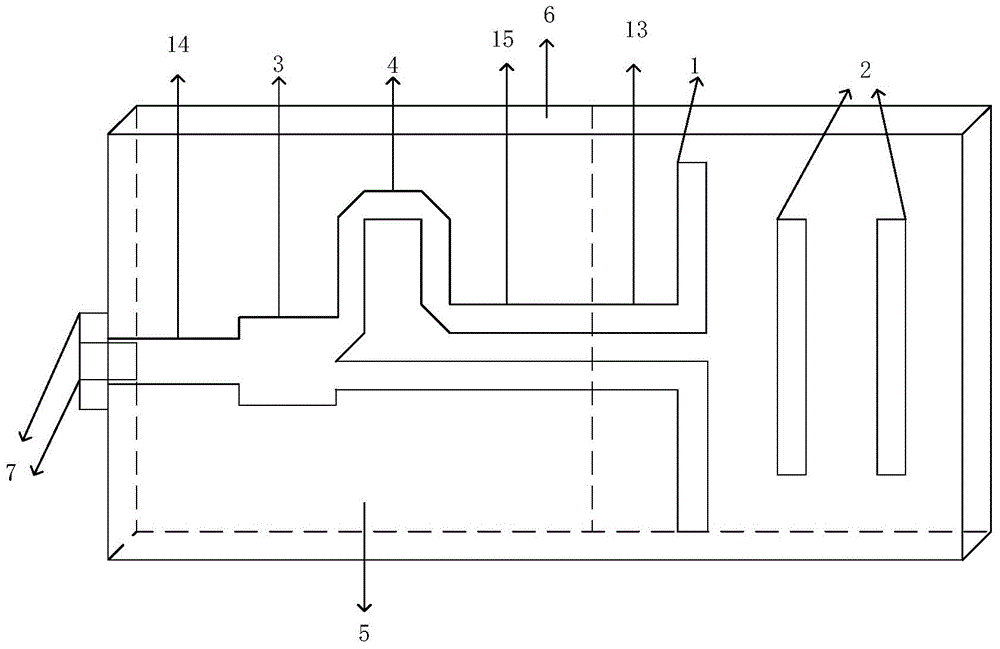
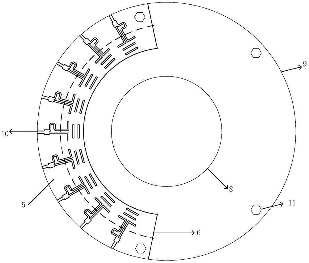
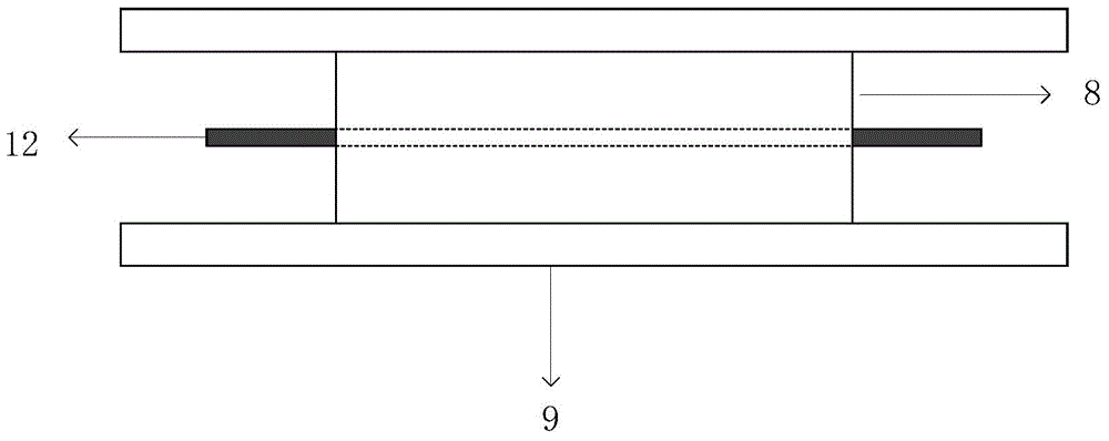
[0017] Embodiment: the diameter of the circular parallel plate waveguide is 79.6mm, the length of the excitation vibrator is 7mm, the length of the director is 4.5mm, the dielectric constant of the dielectric layer is 2.2, and the dielectric constant of the dielectric cylindrical lens is 2.54. The distance between the shaped parallel plate waveguide is 15mm, the length of the planar Yagi antenna is 15.6mm, the working frequency is 18GHZ, the distance between the arc-shaped array elements is 9°, the distance between the arc-shaped array and the dielectric cylinder lens is 4mm, and coaxial feeding is adopted. The spherical wave emitted by the feed is transformed into a plane wave after being refracted by the lens, which improves the gain. The aperture of this kind of dielectric cylindrical lens antenna is very different in the horizontal direction and the vertical direction, so the pattern generated is a fan beam, which can realize narrow beam scanning in the horizontal plane, an...


PUM


Abstract

The invention provides a multi-beam scanning lens antenna. The medium cylindrical lens is placed between two parallel plate waveguide parallel circular metal plate, the feed array by printing curved planar antenna array on the dielectric substrate, the feed array horizontally in round two the edge of the metal between the parallel plate waveguide with a feed array and between parallel circular metal plate four hex pillars fixed, since the antenna system uses spaced circular parallel plate waveguide structure to achieve a single-mode transmission, arc shaped feed array can be well combined with the circular parallel plate in the horizontal plane with good symmetry, reduces the volume of the pitch surface, and the process is simple, low cost, to achieve a balanced feeding dipoles, avoid adding additional reflector structure, planar microstrip Yagi antenna feed structure occupies less volume, can be well combined with the control circuit.

Description

technical field [0001] The invention relates to the field of antenna structure design, in particular to a dielectric lens antenna. Background technique [0002] In the field of radar, with the increasing flight speed and maneuverability of aircraft, the radar system must be able to quickly and accurately measure targets in a wide range of angles and in multiple batches. It is required that the antenna be able to form multiple receiving beams to achieve fast tracking, so multi-beam Electronically scanned antennas are widely used. [0003] Traditional multi-beam antennas include reflector antennas and phased array antennas. The disadvantages of these antennas are complex structures, limited scanning range, large loss, narrow operating frequency band, etc., while multi-beam lens antennas have good symmetry and retain Good optical characteristics, and there is no obstruction to the feed source within a certain range, which can realize scanning in a wide range of angles and work...

Claims


Application Information

Patent Timeline
IPC IPC(8): H01Q1/38H01Q1/48H01Q1/50H01Q19/10H01Q19/06H01Q21/00
Inventor 李建周陈昶吴昌英郑奎松
Owner NORTHWESTERN POLYTECHNICAL UNIV
Learn More