A tunable optical receiver and its tunable filter applied to twdm-pon system
A technology of TWDM-PON and receiver, applied in the field of optical communication, can solve the problems of unfavorable batch production, high equipment dependence, large line dispersion, etc., and achieve the effect of low cost, easy integration, and small size
- Summary
- Abstract
- Description
- Claims
- Application Information
AI Technical Summary
Problems solved by technology
Method used
Image

Examples
Embodiment 1
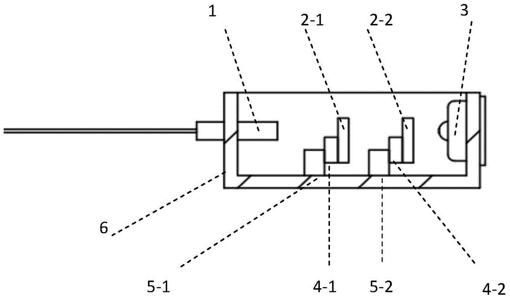
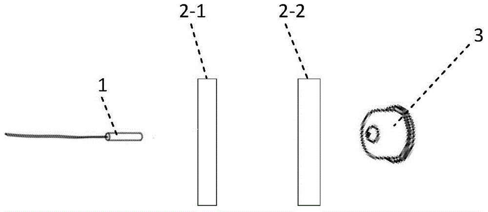
[0044] Take the FSR as 800GHZ, piezoelectric ceramic drive dimmable receiver as an example, such as figure 1 As shown, the package box body 6 includes an incident collimator 1, a first filter etalon 2-1, a second filter etalon 2-2, a packaged APD chip 3, a first piezoelectric ceramic 4-1, a second filter etalon Two piezoelectric ceramics 4-2, a first fixed block 5-1, and a second fixed block 5-2, wherein the incident collimator 1 is aligned with the packaged APD chip 3 and realizes optical path coupling. The first filter etalon 2-1 and the second filter etalon 2-2 are air-based etalons, which are located between the incident collimator 1 and the packaged APD chip 3. They have the same thickness and FSR of 800GHZ. The reflectance of the front and rear surfaces of the etalon is the same, and the reflectance of the surfaces between the two etalons is the same, that is, the reflectances of the four surfaces of the two etalons are all the same, for example, they are all 0.8. One s...
Embodiment 2
[0048] Such as Figure 5 As shown, the package box 6 includes an incident collimator 1, a first filter etalon 2-1, a second filter etalon 2-2, a packaged APD chip 3, and a first fixed block 7 bonded. -1. Bonding the second fixing block 7-2, wherein the incident collimator 1 is aligned with the packaged APD chip 3 to realize optical path coupling. The first filtering etalon 2-1 and the second filtering etalon 2-2 are solid etalons, which are located between the radiation collimator 1 and the packaged APD chip 3. They have the same thickness, and their FSRs are both 800GHZ. The reflectance of the front and rear surfaces of the etalon is the same, and the reflectance of the surfaces between the two etalons is the same, that is, the reflectance of the four surfaces of the two etalons are all the same, for example, they are all 0.8. The material of the solid-state etalon can be a light-transmitting material with a high thermo-optic coefficient such as silicon. The first filter et...
Embodiment 3
[0050] Such as Figure 6 As shown, the first piezoelectric ceramic 4-1 and the second piezoelectric ceramic 4-2 in Embodiment 1 are respectively replaced with the first MEMS driving unit 8-1 and the second MEMS driving unit 8-2, and the rest are not Change. That is: one side of the first filter etalon 2-1 is connected to the first MEMS drive unit 8-1, and is fixed to the bottom surface of the packaging box 6 by bonding the first fixing block 5-1, and the second filter etalon 2-2 One side is connected with the second MEMS driving unit 8-2, and fixed on the bottom surface of the packaging box 6 by sticking the second fixing block 5-2. In this embodiment, the thickness adjustment of the first filter etalon 2-1 and the second filter etalon 2-2 are respectively driven by the first MEMS drive unit 8-1 and the second MEMS drive unit 8-2, and then adjusted. The transmission peak wavelength FSR realizes the tunable working wavelength of the whole tunable receiver.
[0051] Both the ...
PUM
 Abstract
Description
Claims
Application Information
 - R&D
- Intellectual Property
- Life Sciences
- Materials
- Tech Scout
- Unparalleled Data Quality
- Higher Quality Content
- 60% Fewer Hallucinations
Browse by: Latest US Patents, China's latest patents, Technical Efficacy Thesaurus, Application Domain, Technology Topic, Popular Technical Reports.
© 2025 PatSnap. All rights reserved.Legal|Privacy policy|Modern Slavery Act Transparency Statement|Sitemap|About US| Contact US: help@patsnap.com