Eureka AIR delivers breakthrough ideas for toughest innovation challenges, trusted by R&D personnel around the world.

Deep brain stimulation system

A deep brain and EEG signal technology, applied in the field of implantable deep brain stimulation system, can solve the problems of restricting patient's activities, dislocation of electrodes and wires, increasing system energy consumption, etc., and achieve the effect of simple operation process and easy replacement

Active Publication Date: 2015-05-20
LIFETECH SCIENTIFIC (SHENZHEN) CO LTD
View PDF4 Cites 18 Cited by
  • Summary
  • Abstract
  • Description
  • Claims
  • Application Information

AI Technical Summary

Problems solved by technology

[0006] The biggest disadvantages of existing products are: firstly, the existing deep brain stimulation system is an open-loop system, that is, the stimulation mode is continuous stimulation, and the brain tissue is stimulated for a period of time every few minutes after implantation. Increase the energy consumption of the system, and the power supply battery of the system is disposable, and its life span is about 3 to 5 years. Once the battery energy is exhausted, the patient has to undergo surgery again to replace the battery, which increases the pain of the patient and the risk of surgery. It also increased its economic burden; secondly, although the number of epileptic seizures can be significantly reduced after treatment with the deep brain stimulation system, it still cannot completely eliminate epileptic seizures. Because it cannot predict epilepsy, the irregular seizures of epilepsy will make patients potentially dangerous , which will greatly limit some activities of the patient's daily life; finally, the stimulator of the existing deep brain stimulation system is generally implanted under the clavicle or near the chest of the patient, which must be connected to the stimulating electrodes through wires, and Leads are surgically implanted in the patient's scalp and under the skin, which can cause significant problems for the patient during surgery and treatment, such as complications from infection, lack of communication between the stimulator and electrodes, Wire misalignment, etc.

Method used


Image

  • Deep brain stimulation system
  • Deep brain stimulation system
  • Deep brain stimulation system

Examples


Embodiment Construction

[0029] The specific implementation manners of the present invention will be further explained below in conjunction with the accompanying drawings and examples, but the protection scope of the present invention is not limited thereto.

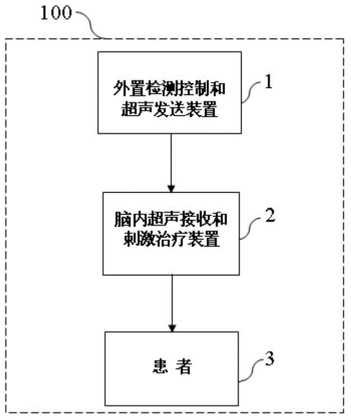
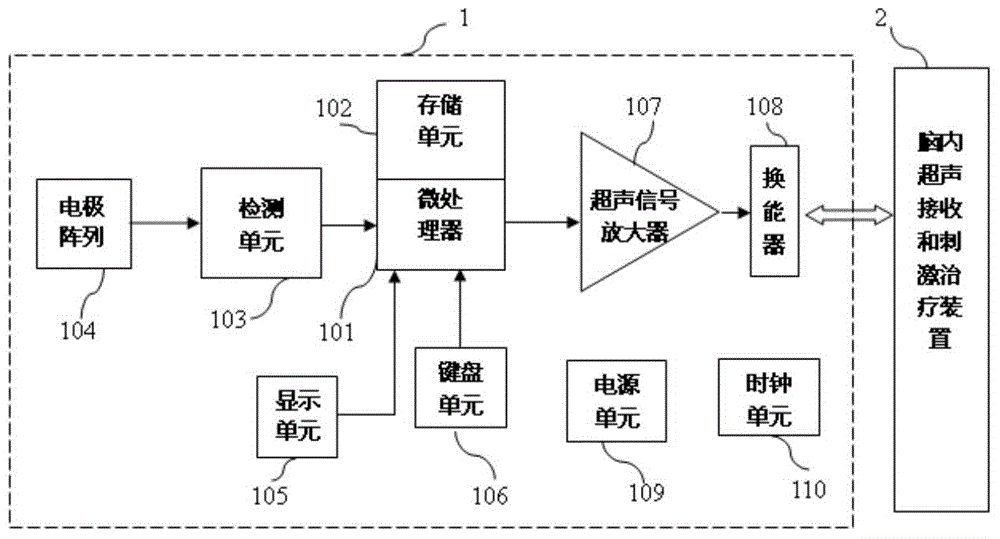
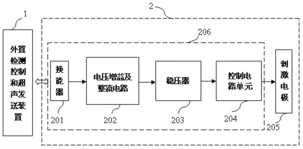
[0030] like figure 1 As shown, the deep brain stimulation system of the present invention mainly includes an external detection control and ultrasonic sending device 1 and an intracerebral ultrasonic receiving and stimulating treatment device 2 . The external detection control and ultrasonic sending device 1 has an epilepsy detection module and an ultrasonic signal generating function, and the intracerebral ultrasonic receiving and stimulating treatment device 2 has an ultrasonic receiving module and an electric pulse stimulating treatment function.

[0031] The external detection control and ultrasonic sending device can be hung on the patient's ear or on a special hat. Among them, the electrode array 104 of the epilepsy detection module is pl...


PUM


Abstract

The invention discloses a deep brain stimulation system which comprises an external detection control and ultrasonic sending device and an intracerebral ultrasonic receiving and stimulation treatment device. The external detection control and ultrasonic sending device is positioned outside the body of a patient and mainly comprises a microprocessor, a storage unit, a detection unit, an electrode array, an ultrasonic signal amplifier, a transducer, a display unit, a keyboard unit, a power source unit and a clock unit, and an intracerebral ultrasonic receiving and stimulation treatment device is implanted deeply in brain tissue of the patient and mainly comprises a transducer, a voltage gain and rectifier circuit, a voltage stabilizer, a control circuit unit and a stimulation electrode. The deep brain stimulation system is used for treatment of nervous system diseases like Parkinson's disease, torsion spasm, spasmodic torticollis, chorea and epilepsy.

Description

field of invention [0001] The invention belongs to the field of medical devices, and relates to a system for treating nervous system diseases, in particular to an implantable deep brain stimulation system, which is used for the treatment of Parkinson's disease, torsion spasm, spastic torticollis, chorea, epilepsy and other nervous system diseases. Background technique [0002] For neurological diseases such as Parkinson's disease, epilepsy, intractable pain, torsion spasm, spastic torticollis, chorea, etc., drug therapy and surgical treatment are commonly used clinically, but side effects and complications are prone to occur. Electrical stimulation therapy, such as deep brain stimulation, performs chronic electrical pulse stimulation on the corresponding targets of different diseases, such as stimulating the thalamic nucleus and globus pallidus for Parkinson's disease, stimulating the vagus nerve for epilepsy, and playing a role in the treatment of causes. A reversible neuro...

Claims


Application Information

Patent Timeline
Patent Type & Authority Applications(China)
IPC IPC(8): A61N1/372A61N1/378
Inventor 刘鹏庄少春崔招焕陈文俊曾莉群
Owner LIFETECH SCIENTIFIC (SHENZHEN) CO LTD
Why Eureka
Eureka Blog
Learn More