Complete device for coal liquefaction

A complete set of equipment, coal liquefaction technology, applied in the preparation of liquid hydrocarbon mixture, petroleum industry, etc., can solve the problems of low red mud catalyst activity, large equipment investment, low system pressure, etc.

Inactive Publication Date: 2015-05-20
李红星
View PDF3 Cites 6 Cited by
  • Summary
  • Abstract
  • Description
  • Claims
  • Application Information

AI Technical Summary

Problems solved by technology

German technology implements online hydrogenation of liquefied crude oil in a high-pressure system to obtain high-quality oil and hydrogen-supplying solvent. The system equipment investment is large, the pressure is high, the process conditions are relatively complicated, and the activity of the red mud catalyst used is low; the United States The HTI process uses an external circulating suspended bed, which requires the use of a circulating pump. The operating conditions are quite harsh, and even become a bottleneck for the stable operation of the device; and the cost of the catalyst is high; the liquefaction reactor of the Japanese process uses a bubbling bed, and the minerals at the bottom are easy to deposit, and the product quality is not good. to be reprocessed
In addition, the Russian process has mild reaction conditions and low system pressure, but the cost of the catalyst is high and the catalyst recovery and early coal treatment procedures are complicated
[0003] CN1438294A proposes a direct coal liquefaction process in which countercurrent loop reactors are connected in series. First, mild hydrocracking is carried out in the countercurrent reactor, and after releasing moisture and phenolic substances, they leave the system first, and the heavy materials are then placed in the loop reactor. Continue hydrogenation to obtain a higher yield of liquefied oil; CN1587351A is a direct coal liquefaction process proposed by Shenhua Group, which is an improved version of the two-stage catalytic liquefaction process in the United States, and has not been verified by large-scale industrial experiments
[0006] From the perspective of process flow, Germany connects distillate oil and solvent hydrofining in series in a high-pressure system, and uses a fixed bed hydrogenation reactor, which has insufficient system stability; the United States uses external circulation suspension bed hydrofining, which has not been industrially verified. , use solvent deashing extraction to increase oil yield; Japanese process is hydrogenation of circulating solvent alone

Method used


Image

  • Complete device for coal liquefaction

Examples


Embodiment Construction

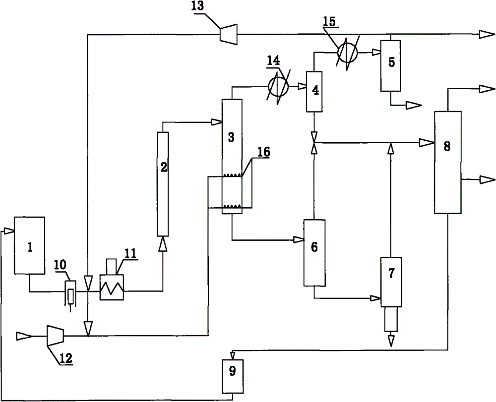
[0020] The present invention will be further described below in conjunction with the accompanying drawings.

[0021] Depend on figure 1 It can be seen that the present invention includes a slurry tank 1, a first reactor 2, a second reactor 3 connected in series with the first reactor 2 and a fractionation tower 8, and the two reactors connected in series are all bubbling bed reactors The second reactor 3 top is provided with a separation space, and its bottom is provided with a gas distributor 16 for deep hydrogenation. The gas distributor 16 is connected with the hydrogen compressor 12 through a pipeline, and the gas distributor 16 can be installed in the second reactor. 3 The lower part is set with 1-5 pieces. The slurry tank 1 is connected to the bottom of the first reactor 2 through the high-pressure coal slurry pump 10 and the coal slurry preheating furnace 11, the output end of the first reactor 2 is connected to the input port on the upper side of the second reactor 3,...


PUM


Abstract

The invention discloses a complete device for coal liquefaction. The complete device comprises a slurrying tank, a first reactor, a second reactor serially connected with the first reactor and a fractionating tower; the slurrying tank is connected with the bottom of the first reactor through a high pressure coal slurry pump and a coal slurry preheating furnace; the output end of the first reactor is connected with the input port of the lateral surface of the upper part of the second reactor; and the second reactor is provided with a bottom outlet and a top outlet, the top outlet is connected with a cooling device, the bottom outlet is connected with a decompression device, and the cooling device and the decompression device are connected with the fractionating tower by pipes. The complete device has the characteristics of brief flow, stable operation and high oil yield.

Description

technical field [0001] The invention relates to a complete set of coal liquefaction equipment. Background technique [0002] At present, there are three main processes for direct coal liquefaction in the world: German IGOR process, American HTI process and Japanese NEDOL process. German technology implements online hydrogenation of liquefied crude oil in a high-pressure system to obtain high-quality oil and hydrogen-supplying solvent. The system equipment investment is large, the pressure is high, the process conditions are relatively complicated, and the activity of the red mud catalyst used is low; the United States The HTI process uses an external circulating suspended bed, which requires the use of a circulating pump. The operating conditions are quite harsh, and even become a bottleneck for the stable operation of the device; and the cost of the catalyst is high; the liquefaction reactor of the Japanese process uses a bubbling bed, and the minerals at the bottom are eas...

Claims


Application Information

Patent Timeline
Patent Type & Authority Applications(China)
IPC IPC(8): C10G1/06
CPCC10G1/065
Inventor 李红星
Owner 李红星
Why Eureka
Try Eureka