Ground source heat pump deep well backfill grouting method

A technology of backfill grouting and ground source heat pump, which is applied in the direction of drilling equipment, earthwork drilling, drill pipe, etc., can solve the problems that ground source heat pump technology cannot be realized, construction quality is difficult to guarantee, and heat exchange effect is poor, so as to improve the construction continuity High performance, high construction efficiency and high compactness

Active Publication Date: 2015-05-20
WUHAN ORIENT CONSTR GROUP +1
View PDF4 Cites 10 Cited by
  • Summary
  • Abstract
  • Description
  • Claims
  • Application Information

AI Technical Summary

Problems solved by technology

[0003] However, at present, this process often uses manual methods to pour mortar materials from the wellhead of deep wells. Due to the small diameter of the well body, the remaining space is small except for the heat exchange pipes. This makes the manual method not only inefficient, but also easy to block in the middle of the deep well, resulting in Completely empty; secondly, manual watering requires the use of slurry w

Method used


Image

  • Ground source heat pump deep well backfill grouting method
  • Ground source heat pump deep well backfill grouting method

Examples


Embodiment 1

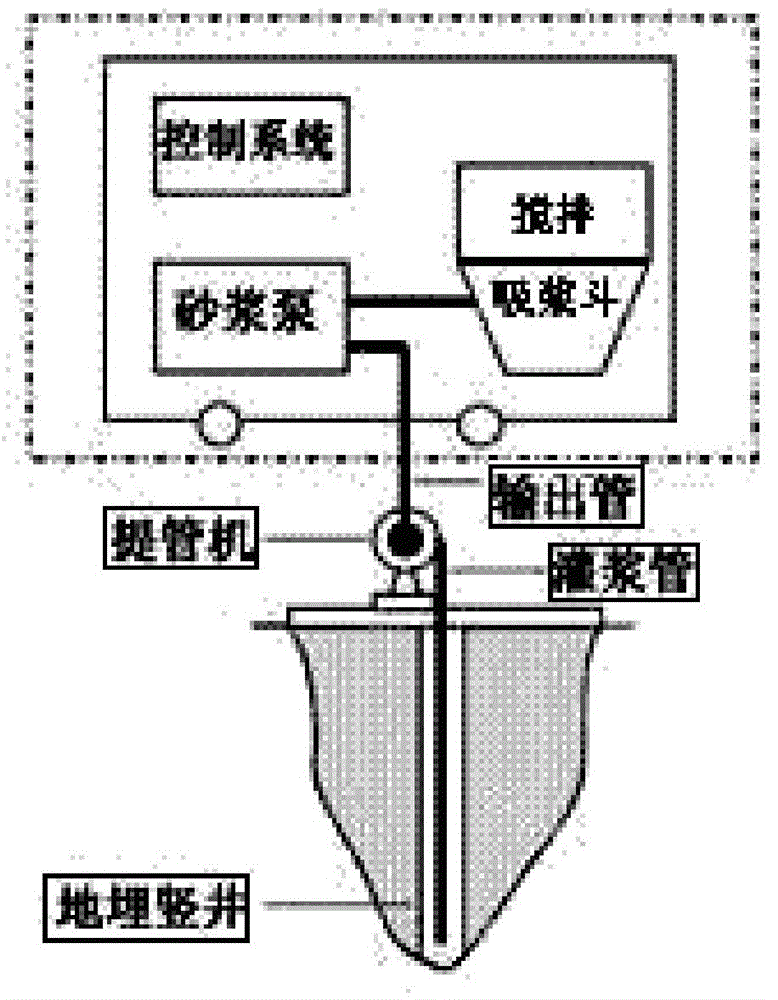
[0028] see Figure 1-2 , The invention provides a ground source heat pump deep well backfill grouting method. This method is also known as back-pressure backfill grouting method of long tubes of ground source heat pump deep wells, which can realize dense backfill grouting without hollowing, greatly improves the heat exchange capacity of deep heat exchange wells, and effectively guarantees the quality of ground source heat pump systems. The ground source heat pump deep well backfill grouting method preferably includes the following steps:

[0029] After setting the heat exchange tubes in the deep well or at the same time, insert the long grouting pipe into the bottom of the deep well;

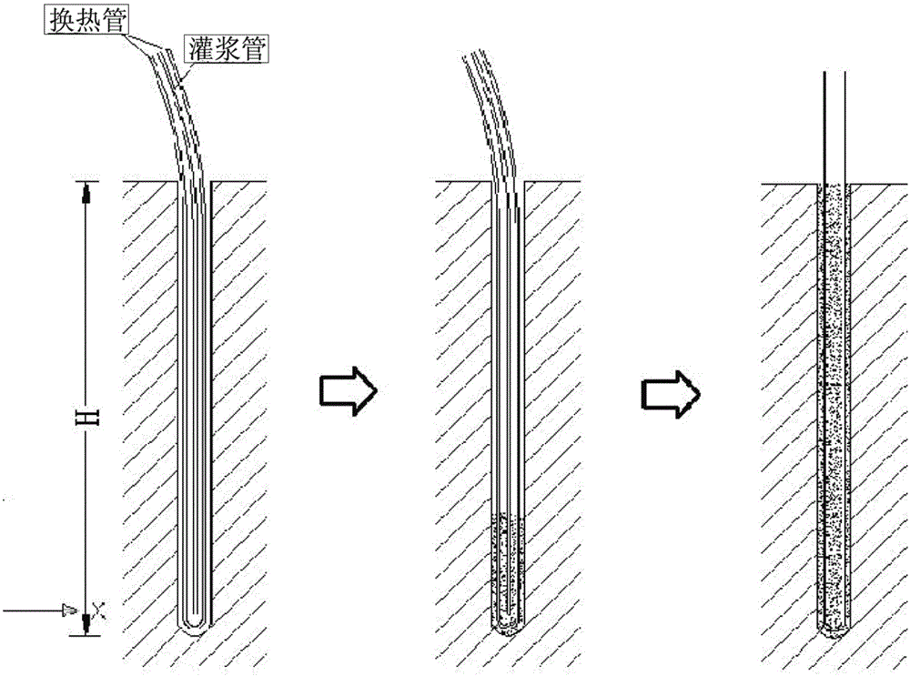
[0030] The backfilling slurry is transported to the bottom of the deep well by the mortar delivery pump (or called the mortar pump) through a long pipe, and the grouting backfills the shaft from the bottom, and the slurry liquid level gradually overflows to form a back pressure;

[0031] When ...

Embodiment 2

[0057] See you again Figure 1-2 , which shows a schematic diagram of the ground source heat pump deep well backfill grouting equipment and method according to a preferred embodiment of the present invention. Preferably, the ground source heat pump deep well backfill grouting method adopts a back pressure backfill construction mode, using a long pipe to insert into the bottom of the deep well, and the backfill slurry is transported to the bottom of the heat exchange deep well by the mortar delivery pump through the long rubber hose, and grouted from the bottom to fill the well with back pressure , the slurry liquid level gradually overflows to form a back pressure. When the slurry liquid level overflows to about 10 meters from the outlet of the grouting pipe, use the pipe lifter to start lifting the grouting pipe. The machine can rotate to wind the pipe and lift it up. It realizes filling while lifting, and the grouting speed matches the pipe lifting speed. Always ensure that ...


PUM


Abstract

The invention provides a ground source heat pump deep well backfill grouting method. The ground source heat pump deep well backfill grouting method is characterized by comprising the following steps that after or while a heat exchange pipe is arranged in a deep well, a long grouting pipe is inserted into the bottom of the deep well; backfill slurry is conveyed to the bottom of the deep well through a slurry conveying pump by means of the long pipe, grouting is conducted at the bottom to fill a well shaft through counter pressure, and the surface of the slurry gradually rises to form back pressure; when the back pressure reaches a first pressure value, the long pipe starts to be lifted, the purpose that while grouting is conducted, the pipe is lifted is achieved, the back pressure is maintained between a second pressure value and the first pressure value until the slurry overflows from a well mouth, and then the whole deep well is filled with the slurry. By the adoption of the ground source heat pump deep well backfill grouting method, the high density of the backfilling slurry is guaranteed, the heat conducting capacity of the heat exchange deep well is greatly improved, the construction quality of a ground source heat pump system is effectively guaranteed, and energy conservation and emission reduction are really achieved.

Description

technical field [0001] The invention relates to a process method for backfilling and grouting construction, in particular to a backfilling and grouting method for deep wells of ground source heat pumps. Background technique [0002] Due to its advantages of environmental protection, high efficiency and energy saving, ground source heat pump technology has developed rapidly in recent years. Among them, vertical buried pipe ground source heat pump has become the mainstream direction of ground source heat pump due to its high heat exchange efficiency and small footprint. This technology requires drilling a large number of small-diameter deep heat exchange wells with a depth of about 80-200m. After the heat exchange tubes are buried, they need to be filled with mortar and other materials with good thermal conductivity. The heat exchange of the heat exchange tube. [0003] However, at present, this process often uses manual methods to pour mortar materials from the wellhead of d...

Claims


Application Information

Patent Timeline
IPC IPC(8): E02D15/04
CPCE02D15/04E21B17/18
Inventor 张声军王军方群英王治耀曹国巍陈炜宁徐毅石小虎周磊
Owner WUHAN ORIENT CONSTR GROUP
Why Eureka
Try Eureka