Spiral type gas-liquid separator under micro-gravity based on porous material

A technology of gas-liquid separator and porous material, which is applied in the field of spiral gas-liquid separator under microgravity, which can solve the problems of insufficient capillary force of the grid inside the wall and limitation of separation volume of the separator, etc.

Active Publication Date: 2015-06-03
ZHEJIANG UNIV
View PDF7 Cites 18 Cited by
  • Summary
  • Abstract
  • Description
  • Claims
  • Application Information

AI Technical Summary

Problems solved by technology

Since the gas-liquid phase separation process in this patent document does not utilize the effect of gravity, it can be well applied to the gas-liquid separation process under microgravity, but because the patent introduces driving mechanisms such

Method used


Image

  • Spiral type gas-liquid separator under micro-gravity based on porous material
  • Spiral type gas-liquid separator under micro-gravity based on porous material
  • Spiral type gas-liquid separator under micro-gravity based on porous material

Examples


Embodiment 1

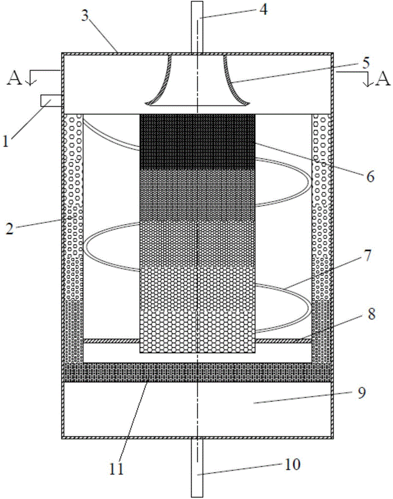
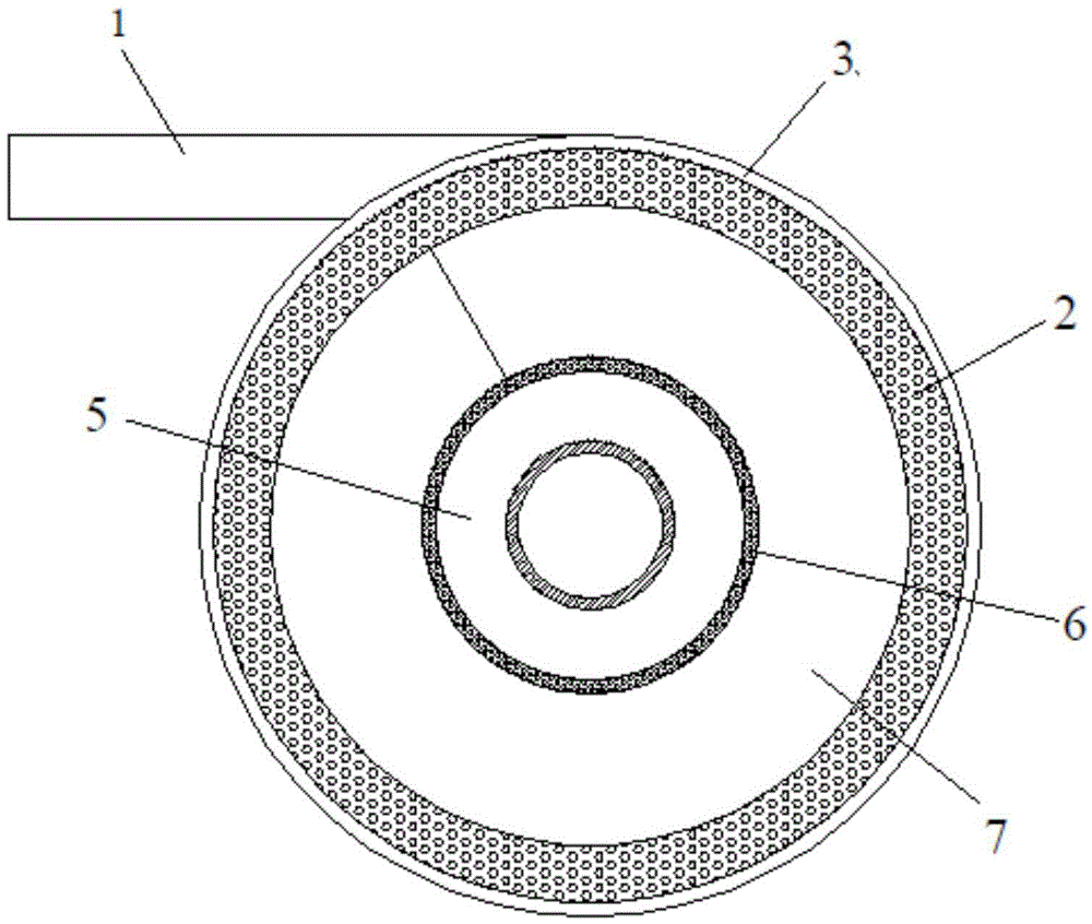
[0038] In order to reduce the pressure of logistics support in space missions, the CO in the spacecraft 2 and H 2 The treatment and recovery of O and other substances mainly rely on the regeneration of the annular space and the life support system, and the gas-liquid separation process is a key link in the system. This example illustrates the application of a porous material-based spiral gas-liquid under microgravity in the regenerative annular space and life support system proposed by the present invention. Set the reclaimed substance to be liquid water, the selection of the porous wall material in this embodiment is a hydrophilic material (such as polyacrylonitrile material, polysulfone material, etc.), and the capillary core of the center is selected as a hydrophobic material (such as polytetrafluoroethylene vinyl, etc.). The liquid phase outlet 10 of the separator is arranged at the bottom center of the housing 3, so the density distribution of the porous material on the...

Embodiment 2

[0045] This example illustrates the application of a microgravity spiral gas-liquid separator based on porous materials proposed by the present invention in a vapor compression system. The working fluid used in this example is set to be R134a, the porous material on the tube wall is selected as a material that R134a can wet well, and the capillary core in the center is selected as a material that R134a cannot wet well. The liquid phase outlet 10 of the separator is arranged at the center of the bottom, so the density distribution of the porous material on the wall is as attached. figure 1 shown.

[0046] After the R134a in the state of gas-liquid two-phase flow flows into the gas-liquid separator through the mixed fluid inlet 1, it makes a spiral movement in the separator under the action of the spiral baffle 7. Due to the difference in the density of R134a in the gas phase and R134a in the liquid phase, the R134a in the gas phase and the R134a in the liquid phase are distrib...

Embodiment 3

[0052] The oxygen currently used in spacecraft is regenerated by electrolysis of water. In order to obtain gaseous oxygen and recover excess water, H 2 O-O 2 the separation process. This example illustrates the application of a microgravity spiral gas-liquid separator based on porous materials proposed by the present invention in an electrolytic oxygen production system. In this example, the porous material of the wall is selected as a hydrophilic material, while the capillary core in the center is selected as a hydrophobic material. The liquid phase outlet of the separator is arranged at the center of the bottom, so the density distribution of the porous material on the wall is as follows: figure 2 shown.

[0053] H after pretreatment 2 O-O 2 The mixed fluid enters the gas-liquid separator along the tangential direction through the mixed fluid inlet. When passing through the helically arranged baffles, due to the centrifugal force, gaseous oxygen and oxygen bubbles are...


PUM


Abstract

The invention discloses a spiral type gas-liquid separator under micro-gravity based on a porous material. The spiral type gas-liquid separator comprises a shell, wherein the shell is provided with a mixed fluid inlet, a gas-phase working medium outlet and a liquid-phase working medium outlet; the shell is internally provided with a hydrophobic-phase porous material column located at the axis of the shell, a lyophilic-phase porous material layer located on the inner wall of the shell, and a baffle plate is arranged between the hydrophobic-phase porous material column and the lyophilic-phase porous material layer and is in spiral arrangement along the axial direction of the shell; and the two side edges of the baffle plate are fixedly connected with the outer wall of the hydrophobic-phase porous material column and the inner wall of the lyophilic-phase porous material layer respectively. Therefore, the spiral type gas-liquid separator under the micro-gravity based on the porous material combines the advantages of a static separator and a dynamic separator; and meanwhile, the respective disadvantages are also overcome. The spiral type gas-liquid separator has the advantages of great gas-liquid separation amount, no power consumption, high reliability and the like and has a very good application prospect under a micro-gravity environment.

Description

technical field [0001] The invention relates to a gas-liquid separator, in particular to a spiral gas-liquid separator based on porous materials under microgravity. Background technique [0002] Since the 1950s, the aerospace industry has developed vigorously, and human activities in space have become more and more frequent. The development level of the aerospace industry has become an important indicator for evaluating a country's scientific research capabilities. Among them, the fluid management technology under microgravity As an important part of aerospace technology, it has been widely valued by all countries. Microgravity fluid management technology refers to the control of fluid transportation and storage in microgravity environment, so that a certain system can operate and complete the required functions. From the perspective of engineering application, fluid management technology in microgravity is mainly used in the following systems of spacecraft: 1) Propellant m...

Claims


Application Information

Patent Timeline
IPC IPC(8): B01D19/00C02F1/20
Inventor 韩晓红王学会方一波乔晓刚鹿丁王勤陈光明
Owner ZHEJIANG UNIV
Why Eureka
Try Eureka