
Device and method for blowing ash in entrained flow gasifier

A technology of soot blowing device and gasifier, which is applied in the mechanical details of gasification device, gasification process, granular/powdered fuel gasification, etc., and can solve the problems of equipment failure, fly ash difficulty, and large amount of purge gas, etc. problems, to achieve the effect of reducing the cohesiveness of fly ash, good effect of soot blowing, and small gas consumption of soot blowing

Active Publication Date: 2015-06-03
HUANENG TIANJIN COAL GASIFICATION POWER CO LTD
View PDF8 Cites 1 Cited by
  • Summary
  • Abstract
  • Description
  • Claims
  • Application Information

AI Technical Summary

Problems solved by technology

Since fly ash is carried in the gas, and fly ash is sticky at high temperature, the fly ash will bond on the heating surface of the arranged water-cooled wall. When the bonding bottom layer is formed, the fly ash will be more easily bonded to the heating surface The bonded fly ash is not easy to be taken away by the gas, thus blocking the gas channel and forming ash blockage, resulting in the failure of normal operation of the equipment
[0004] At present, there is an existing device, which adopts the intermittent soot blowing method. When the fly ash is deposited on the heating surface of the water wall, the bonded ash is blown away with a large instantaneous air volume, which is a method of post-processing. The blowing gas volume is large, and it is not easy to blow off the ash

Method used


Image

  • Device and method for blowing ash in entrained flow gasifier
  • Device and method for blowing ash in entrained flow gasifier
  • Device and method for blowing ash in entrained flow gasifier

Examples


Embodiment Construction

[0021] The present invention will be described in further detail below in conjunction with the accompanying drawings and specific embodiments.

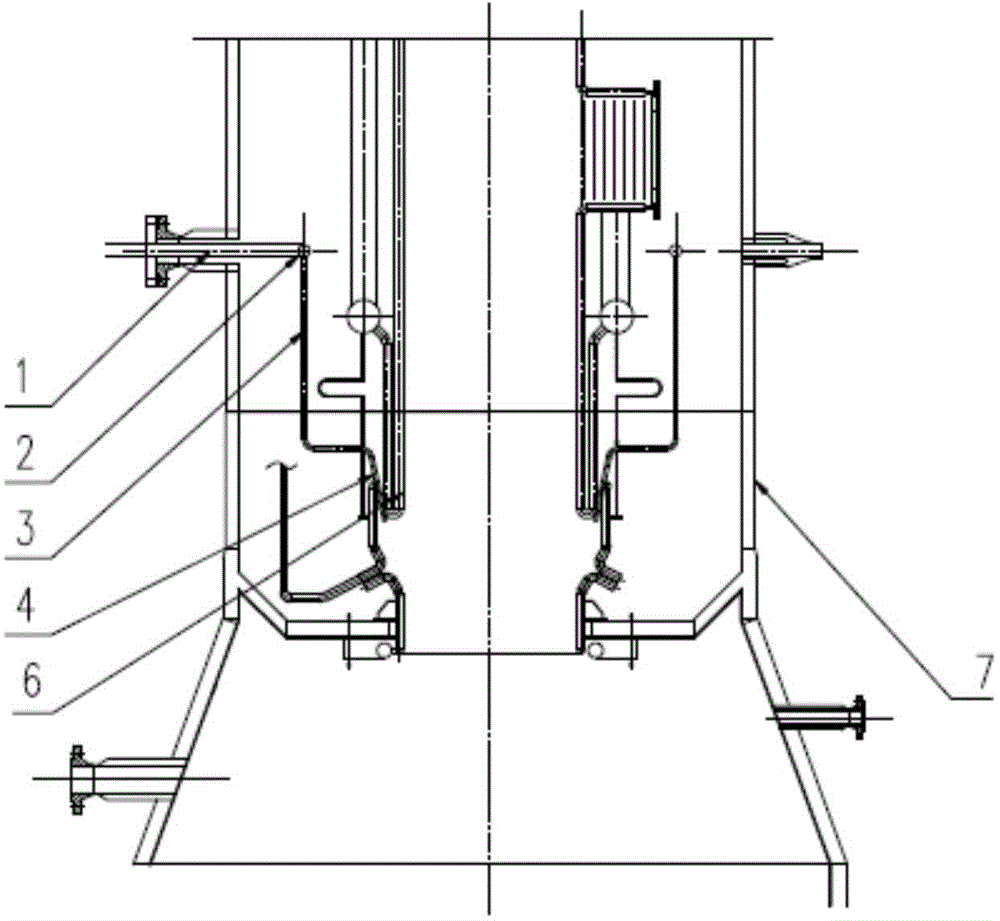
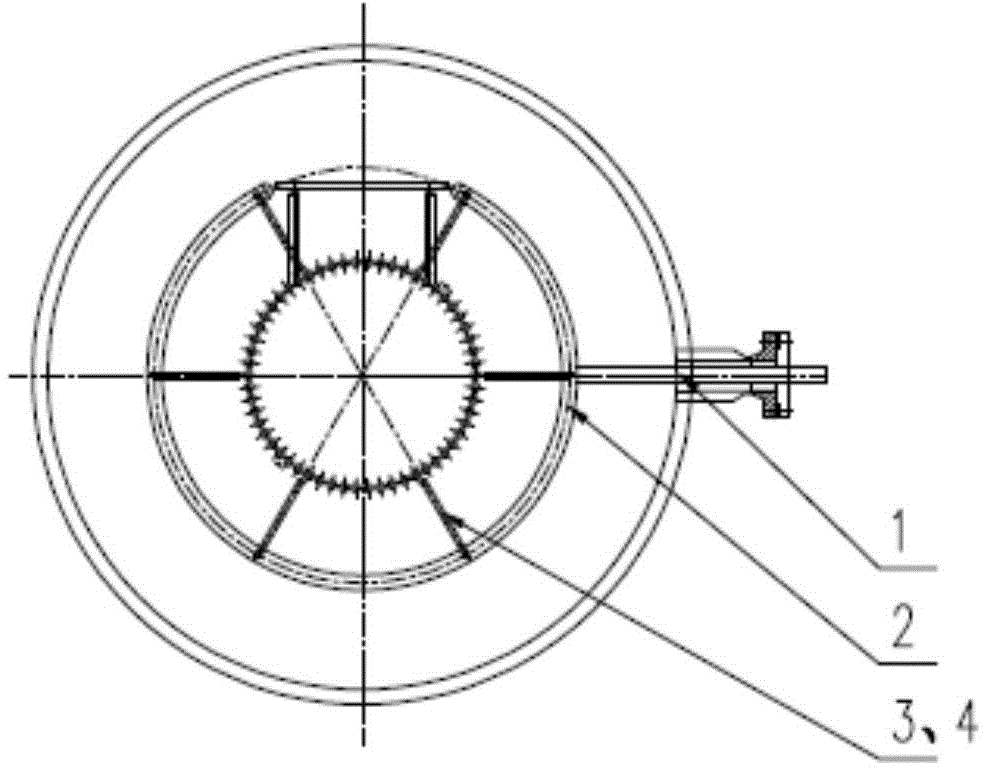
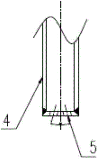
[0022] like Figure 1a , Figure 1b , Figure 2a and Figure 2b As shown, the present invention is a soot blowing device used in an entrained bed gasifier, including a soot blower pipe joint 1 welded on the gasifier shell 7 and extending into it, arranged on the gasifier shell 7 The annular soot blower main pipe 2 connected with the soot blower pipe joint 1 between the water wall 6 of the gasifier, the multiple first soot blower branch pipes 3 communicated with the annular soot blower main pipe 2, and each first The second soot blower branch pipe 4 communicated with the soot blower branch pipe 3, the second soot blower branch pipe 4 passes through the water cooling wall 6 of the gasification furnace, and is arranged on the inner surface of the water cooling wall 6 of the gasification furnace, and the second soot blower branch pipe ...


PUM


Abstract

The invention discloses a device and a method for blowing ash in an entrained flow gasifier. The device comprises a pipe joint, an annular main pipe, a plurality of first branch pipes and a plurality of second branch pipes, wherein the pipe joint is welded on the shell of the entrained flow gasifier and extends into the entrained flow gasifier, the annular main pipe is arranged between the shell of the entrained flow gasifier and the water cooled wall of the entrained flow gasifier and is connected with the pipe joint, the first branch pipes are communicated with the annular main pipe, and the second branch pipes are communicated with the first ash blower branch pipes respectively, penetrate through the water cooled wall of the entrained flow gasifier and are arranged on the inner surface of the water cooled wall of the entrained flow gasifier. The head part of each second ash blower branch pipe is provided with two small holes, and the small holes are aligned to the ash deposition position of the water cooled wall 6 of the entrained flow gasifier. The method comprises the following steps: introducing N2 or CO2 into the device, and blowing the surface of the water cooled wall of the entrained flow gasifier continuously through the small holes to prevent the deposition of ash. By adopting the device and the method, the deposition of the ash and the formation of an adhesive bottom layer can be inhibited, the flying ash can be blown away before being adhered onto the heated surface, and the adhesion of the flying ash can be reduced. The device and the method have the characteristics of good ash blowing effect and low consumption of gases for ash blowing.

Description

technical field [0001] The invention relates to the technical field of coal-based synthesis gas dedusting, in particular to a soot blowing device and a soot blowing method used in an entrained bed gasification furnace. Background technique [0002] Entrained bed gasification is an important form of coal gasification. The raw coal is fed into the furnace in powder form. The pulverized coal and gasification agent are sprayed into the gasifier through nozzles or burners, and are fully mixed and Combustion and gasification reactions. The gasification furnace provides a reaction space for the gasification reaction. The reaction temperature of the entrained bed gasification is very high, generally maintained at a high temperature of 1400-1600 ° C, thus ensuring the complete conversion of carbon. After the high-temperature gas leaves the gasifier, the temperature of the gas needs to be lowered. Generally, there are two ways to reduce the temperature: water-cooled wall tube heat ex...

Claims


Application Information

Patent Timeline
IPC IPC(8): C10J3/72C10J3/48
CPCC10J3/485C10J3/72C10J2200/09C10J2300/16C10J2300/1628
Inventor 许世森李广宇李小宇任永强夏军仓刘刚陶继业王恩民陈智
Owner HUANENG TIANJIN COAL GASIFICATION POWER CO LTD
Learn More