Eureka AIR delivers breakthrough ideas for toughest innovation challenges, trusted by R&D personnel around the world.

Fault-tolerant operation method of switched reluctance motor speed control system based on simplified flux linkage method

A technology of switched reluctance motor and speed control system, which is applied in control systems, control generators, vector control systems, etc., can solve the problems of paralysis of the operation system and disorder of position estimation signals, and achieve the effect of improving operation stability.

Active Publication Date: 2017-04-26
山东贝斯特电动工具有限公司
View PDF9 Cites 0 Cited by
  • Summary
  • Abstract
  • Description
  • Claims
  • Application Information

AI Technical Summary

Problems solved by technology

[0004] Position sensorless control technology, such as the simplified flux linkage method, that is, the delay method simplifies the flux linkage position estimation method, and uses current sensors and voltage sensors to measure voltage and current, so as to calculate the flux linkage value through voltage and current, thereby judging the position of the rotor , and then output the position signal, that is, the instruction of delaying the turn-on or turn-off, and controlling the switching of the motor winding, so as to realize the stable operation of the motor without a position sensor. , switch tube failure, etc., when the current / voltage sensor fails, the position estimation signal will be disordered, which will seriously cause the operating system to be paralyzed. Fault Tolerant Techniques for Position Estimation in Fault Conditions

Method used


Image

  • Fault-tolerant operation method of switched reluctance motor speed control system based on simplified flux linkage method
  • Fault-tolerant operation method of switched reluctance motor speed control system based on simplified flux linkage method
  • Fault-tolerant operation method of switched reluctance motor speed control system based on simplified flux linkage method

Examples


Embodiment Construction

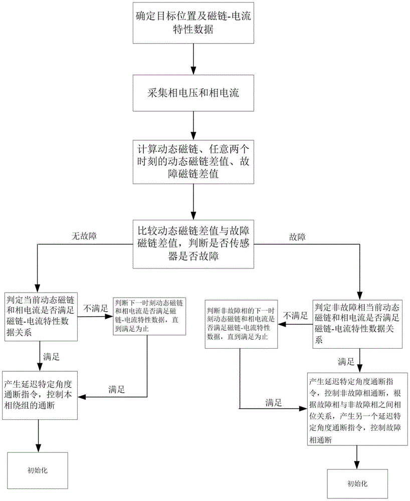
[0022] A fault-tolerant operation method for a switched reluctance motor speed control system based on a simplified flux linkage method. The switched reluctance motor system includes a switched reluctance motor, a power converter unit for driving the switched reluctance motor, and signal acquisition and processing for collecting phase current and phase voltage unit and a control unit, the method includes the steps of:

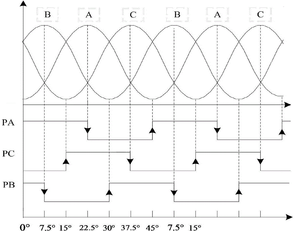
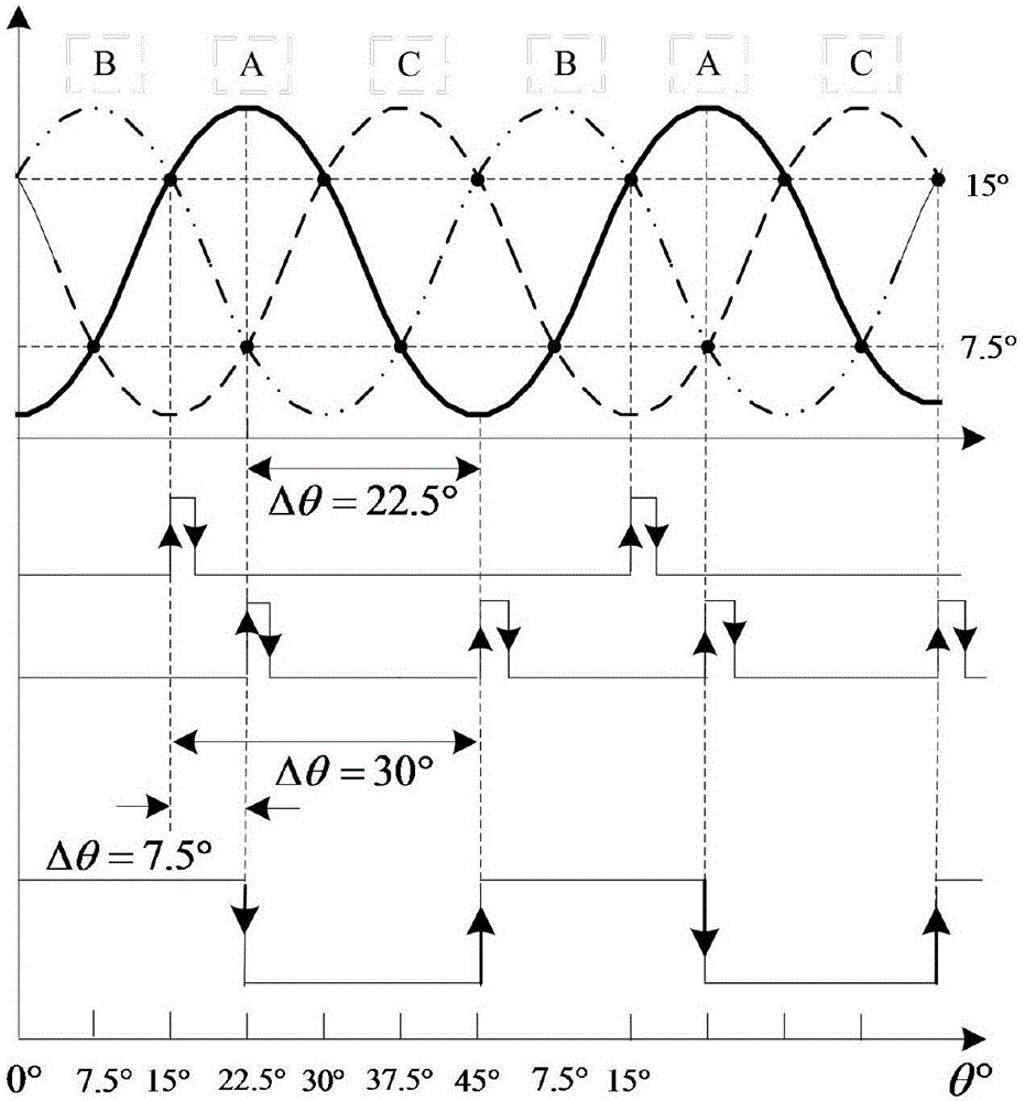
[0023] Step 1: Select the rotor position corresponding to the intersection point of the phase inductance curve, and define it as the target position. At the target position, measure the flux linkage-current characteristic data of the phase winding, and store the flux linkage-current characteristic data in the control unit;

[0024] Step 2 The signal acquisition and processing unit collects the phase voltage and phase current in real time, and converts the phase voltage value U k and phase current value i k transmitted to the control unit;

[0025] Step 3 Star...


PUM


Abstract

The invention discloses a simplified flux method-based fault tolerance operation method for a switched reluctance motor speed adjusting system, aiming at faults of current sensors or voltage sensors. The fault tolerance operation method comprises the following steps: selecting a target position, measuring flux-current characteristic data, acquiring phase current voltage, calculating dynamic flux and a different value of dynamic fluxes at any two moments, calculating fault flux, judging whether the difference value of the dynamic fluxes is identical to a fault flux value or not, if the difference value of the dynamic fluxes is identical to the fault flux value, confirming that a sensor has faults, and transmitting an instruction for delaying fault phase control according to electromagnetic signals of a normal phase winding, if the difference value of the dynamic fluxes is not identical to the fault flux value, confirming that the sensor has not fault, and transmitting an instruction for delaying on / off control on the phase winding according to the electromagnetic signals of the phase winding. By adopting the fault tolerance operation method, a switched reluctance motor without a position sensor can still correctly estimate the position of a rotor under the situation that certain current sensors or voltage sensors have faults, and the operation stability of a switched reluctance motor system is improved.

Description

technical field [0001] The invention relates to the technical field of switched reluctance motor control, in particular to a fault-tolerant operation method of a switched reluctance motor speed regulation system based on a simplified flux linkage method for faults of current sensors or voltage sensors. Background technique [0002] Since the successful research and development of switched reluctance motor by universities such as Leeds in the United Kingdom in the 1980s, it has attracted the attention of many scholars and has had a great impact in the field of transmission. Rapid development. The switched reluctance motor has a double-salient pole structure, and there is no rare earth material on the rotor. It is only made of silicon steel sheets laminated, and the winding coil is on the stator. Therefore, it is simpler and stronger than DC motors, AC motors and asynchronous motors. The motor has fewer processing procedures. Low cost, easy to cool, especially suitable for hi...

Claims


Application Information

Patent Timeline
IPC IPC(8): H02P21/24H02P25/08
Inventor 张磊孙刚徐开军兴志
Owner 山东贝斯特电动工具有限公司
Why Eureka
Eureka Blog
Learn More