Eureka AIR delivers breakthrough ideas for toughest innovation challenges, trusted by R&D personnel around the world.

System and method for three-dimensional characterization of blade tip gaps and dynamic detection of optical fibers of aero-engine

An aero-engine and blade tip clearance technology, applied in the field of aero-engines, can solve the problems of inability to accurately extract fault features, no detection environment compensation method, detection signal confusion, etc.

Active Publication Date: 2015-06-10
XI AN JIAOTONG UNIV
View PDF6 Cites 24 Cited by
  • Summary
  • Abstract
  • Description
  • Claims
  • Application Information

AI Technical Summary

Problems solved by technology

When the compressor and turbine fail, the rotor dynamics behavior is highly nonlinear, and neither the blade tip timing detection method nor the blade tip radial clearance detection method can accurately extract all fault characteristics, and there is also the possibility that the detection signal is easily confused. defects, resulting in misdiagnosis
In addition, in the existing detection technology, electromagnetic sensors such as capacitive sensors are prone to interference due to the gas ionization phenomenon in the high-pressure and high-temperature environment of compressors and turbines; existing optical measurement methods such as Doppler optical fiber displacement sensors The spatial resolution is low, and only the average radial clearance value of the blade tip clearance can be measured, while the light intensity modulation displacement sensor is easily affected by the refractive index fluctuation under the full working conditions of the engine, and the detection results have high nonlinear interference. Surrounding optical fiber sensors (such as double-coaxial optical fiber) can only compensate for the influence of common-mode interference due to light source fluctuations, optical fiber manufacturing processes, and changes in the reflectivity of reflective surfaces, and cannot eliminate the nonlinear environmental interference of the engine under all operating conditions. impact of results
In addition, judging from the patent topics related to blade tip clearance detection that can be retrieved so far, there are research contents that analyze the concentricity of the rotor and stator from the runout value of the blade tip clearance detection results, and also extract The research content of the concave cavity information on the tip surface, the main invention content mostly focuses on the processing and identification method of the radial tip clearance detection signal, and does not involve the full-field three-dimensional dynamic description of the tip clearance and the three-dimensional space of the tip clearance. It does not involve the research on the compensation method for the detection environment of the aero-engine under all working conditions.

Method used


Image

  • System and method for three-dimensional characterization of blade tip gaps and dynamic detection of optical fibers of aero-engine
  • System and method for three-dimensional characterization of blade tip gaps and dynamic detection of optical fibers of aero-engine
  • System and method for three-dimensional characterization of blade tip gaps and dynamic detection of optical fibers of aero-engine

Examples


Embodiment Construction

[0041] The present invention is described in further detail below in conjunction with accompanying drawing:

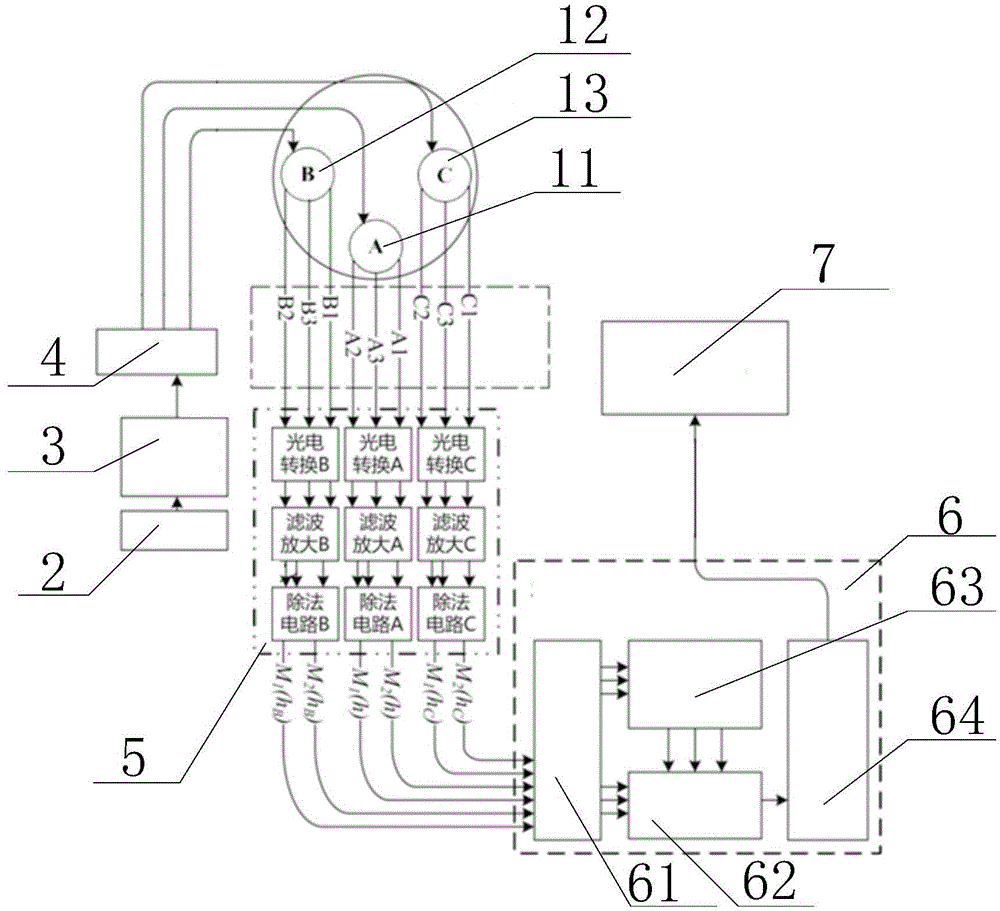
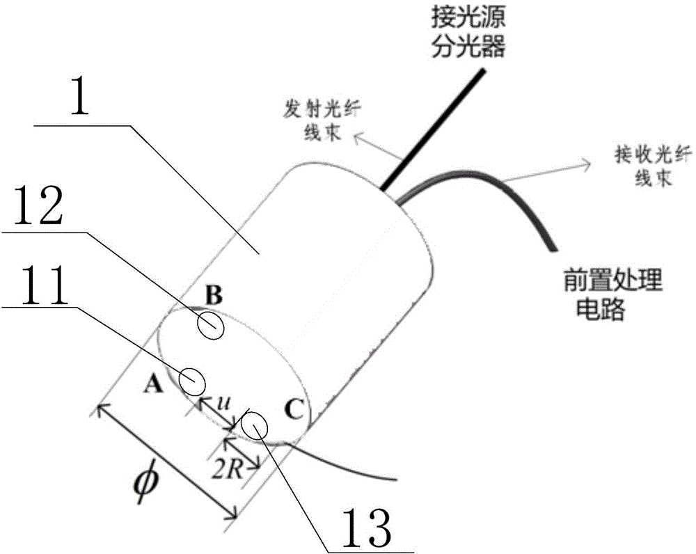
[0042] refer to figure 1 , figure 2 and image 3 The device for three-dimensional characterization and optical fiber dynamic detection of aeroengine tip clearances according to the present invention includes a laser light source 2, a pulse light source control circuit 3, a beam splitter 4, a three-dimensional sensing probe 1 for tip clearances, a preprocessing circuit 5, and a single-chip microcomputer 6 And host computer 7;

[0043] The blade gap three-dimensional sensing probe 1 includes a reference fiber unit 11, an axial angle measurement fiber unit 13 and a circumferential angle measurement fiber unit 12, the connection line between the reference fiber unit 11 and the circumference angle measurement fiber unit 12 and the reference fiber unit 11 and the axial angle measuring fiber unit 13 are perpendicular to each other, the reference fiber unit 11, the axial a...


PUM


Abstract

The invention discloses a system and a method for three-dimensional characterization of blade tip gaps and dynamic detection of optical fibers of an aero-engine. The system comprises a laser light source, a pulsed light source control circuit, a light splitter, a blade tip gap sensing probe, a pre-processing circuit, a single chip and an upper computer; the blade tip gap sensing probe comprises a reference optical fiber, an axial angle-measuring optical fiber and a circumferential angle-measuring optical fiber. The system is capable of dynamically and accurately obtaining the three-dimensional characterization of blade tip gaps of the aero-engine and is high in anti-interference capability.

Description

technical field [0001] The invention belongs to the field of aero-engines, relates to a detection system and method, and specifically designs an aero-engine blade tip clearance three-dimensional representation and optical fiber dynamic detection system and method. Background technique [0002] The aero-engine is the most important part of an aircraft, and the compressor and turbine in it can convert air kinetic energy and high-temperature internal energy into flight kinetic energy, and are the key structures in the engine. Under the full working conditions of the engine during aircraft flight, the compressor and turbine components are subjected to the coupling effect of various loads such as high centrifugal load, aerodynamic load, high temperature thermal load and rotor vibration alternating load, which increases the pressure of the compressor. Chances of machine and turbine failure. According to statistics, compressor and turbine failures account for more than 42% of the ...

Claims


Application Information

Patent Timeline
Patent Type & Authority Applications(China)
IPC IPC(8): G01M15/00G01B11/14
Inventor 张小栋谢思莹牛杭董晓妮郭琦赵欣丹
Owner XI AN JIAOTONG UNIV
Why Eureka
Eureka Blog
Learn More