Optical image reinforcing method and optical image reinforcing device

An optical image and enhancement device technology, applied in the field of optical images, to achieve wide practical value, improve practicability, and achieve the effect of optical enhancement

Active Publication Date: 2015-06-24
TECHNICAL INST OF PHYSICS & CHEMISTRY - CHINESE ACAD OF SCI
View PDF3 Cites 2 Cited by
  • Summary
  • Abstract
  • Description
  • Claims
  • Application Information

AI Technical Summary

Problems solved by technology

[0006] The invention provides an optical image enhancement method and device to solve the technical problem in the prior art that neither the image transmission fiber bundle nor a single nonlinear optical fiber can perform optical enhancement of the image

Method used


Image

  • Optical image reinforcing method and optical image reinforcing device
  • Optical image reinforcing method and optical image reinforcing device
  • Optical image reinforcing method and optical image reinforcing device

Examples


Embodiment 1

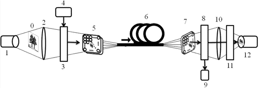
[0088] In this embodiment 1, a transmission imaging is performed on the target object, using 1455nm pump light and 1520nm signal light, and using DCF to perform image enhancement based on SRS. see Figure 5 , Figure 6 .

[0089] Step 5a: Actively illuminate the target object with a signal light source.

[0090] In the embodiment of the present invention, the pulsed laser 101 is used to generate pulsed laser light with a wavelength of 1520 nm as the signal light, and the generated signal light has a pulse width of 100 ns and a frequency of 10 Hz. The generated signal light actively illuminates the target object 0 via the signal light shaping mirror 102 and the emitting mirror 103 .

[0091] Step 5b: Imaging the image signal generated by the target object by means of transmission.

[0092] In this step, the signal light passes through the target object 0 , carries target image information, and is imaged through the input imaging lens 201 .

[0093] Step 5c: using a pump la...

Embodiment 2

[0110] In this embodiment 2, reflective imaging is performed on the target object, using 1553nm pump light and 1574nm signal light, and a single-pump fiber parametric amplifier based on the FWM effect for image enhancement. see Figure 7 , Figure 8 .

[0111] Step 7a: Actively illuminate the target object with a signal light source.

[0112] In the embodiment of the present invention, a pulsed laser 101 is used to generate pulsed laser light with a wavelength of 1574 nm as signal light, the pulse width of the generated signal light is 10 ns, and the repetition frequency is 10 Hz, and the generated signal light passes through the signal light shaping mirror 102 and The reflector 103 actively illuminates the target object 0 .

[0113] Step 7b: Imaging the image signal generated by the target object by means of reflection.

[0114] In this step, the signal light is incident on the target object 0 , and carries target image information after reflection, and is imaged by the i...

Embodiment 3

[0131] In this embodiment 3, the target object is imaged in a transmission mode, using 1539nm pump light and 1518nm signal light, and a single-pump fiber parametric amplifier based on the FWM effect for image enhancement. see Figure 9 , Figure 10 .

[0132] Step 9a: Actively illuminate the target object with a signal light source.

[0133] In the embodiment of the present invention, a pulsed laser 101 is used to generate pulsed laser light with a wavelength of 1518 nm as signal light, the pulse width of the generated signal light is 1 ns, and the repetition frequency is 100 Hz, and the generated signal light passes through the signal light shaping mirror 102 and The reflector 103 actively illuminates the target object 0 .

[0134] Step 9b: Imaging the image signal generated by the target object by means of transmission.

[0135] In this step, the signal light passes through the target object 0 , carries target image information, and is imaged through the input imaging le...


PUM

PropertyMeasurementUnit
wavelengthaaaaaaaaaa
areaaaaaaaaaaa
lengthaaaaaaaaaa

Abstract

The invention provides an optical image reinforcing method and an optical image reinforcing device. The optical image reinforcing method comprises the following steps of imaging a target object to obtain image signal light; generating and transmitting pumping laser by using a pumping laser source; coupling the pumping laser and the image signal light and then inputting the pumping laser and the image signal light into a non-linear optical fiber image transmitting beam; corresponding each optical fiber to a corresponding pixel point of an image; meeting phase matching conditions in a non-linear optical process by selecting pumping laser wavelengths, image signal light wavelengths and optical fiber parameters; inputting and reinforcing weak signals of the various pixel points of the image by using the non-linear optical fiber image transmitting beam; and outputting the image signal light which is reinforced by the pixel points in parallel so as to form an image. By the optical image reinforcing method and the optical image reinforcing device, an optical image is divided into a series of pixel units point by point, and image signals are transmitted and reinforced by the non-linear optical fiber beam. Compared with a method of reinforcing signals by using a single non-linear optical fiber in the prior art, the optical image reinforcing method has high practical value.

Description

technical field [0001] The invention relates to the technical field of optical images, in particular to an optical image enhancement method and device. Background technique [0002] Conventional optical fibers have been widely used in the field of image transmission. For example, endoscopes, which are widely used in medical and industrial fields, use soft optical fiber image transmission bundles to achieve the purpose of image transmission. The image transmission bundle is a fiber optic component that regularly gathers a number of optical fibers of a certain length into a bundle to transmit images. Each optical fiber has a good optical isolation effect, and its independent light transmission surface is not affected by other adjacent optical fibers. , but in general, it is mainly used to transmit images without optical gain. Existing optical signal enhancement technologies include: doped ion fiber amplifier (such as erbium-doped EDFA), laser amplifier, semiconductor optical...

Claims


Application Information

Patent Timeline
Patent Type & Authority Applications(China)
IPC IPC(8): G02F1/39
CPCG02F1/395
Inventor 杨晶许祖彦李小青彭钦军张景园
Owner TECHNICAL INST OF PHYSICS & CHEMISTRY - CHINESE ACAD OF SCI
Why Eureka
Try Eureka