
Electric vehicle advancing type wireless charging device and control method thereof

A technology for electric vehicles and wireless charging, applied in electric vehicles, battery circuit devices, circuit devices, etc., can solve the problems of battery impedance characteristics change, affecting resonance point retention, resonance point offset, etc., to reduce sensitivity and centering performance requirements, achieve impedance matching, and reduce the effect of impact

Inactive Publication Date: 2015-07-01
SOUTH CHINA UNIV OF TECH
View PDF4 Cites 18 Cited by
  • Summary
  • Abstract
  • Description
  • Claims
  • Application Information

AI Technical Summary

Problems solved by technology

Although this technology does not have high requirements on distance and neutrality, there are still the following problems in order to realize charging of electric vehicles during driving: 1) Charging during wireless power transmission, the mutual inductance of the two coils will change, and the resonance point will shift ; 2) The impedance characteristics of the battery will vary with the stored power, which will also affect the maintenance of the resonance point; 3) To realize the uninterrupted charging of the electric vehicle during the driving process, the cost of coil laying is very high

Method used


Image

  • Electric vehicle advancing type wireless charging device and control method thereof
  • Electric vehicle advancing type wireless charging device and control method thereof
  • Electric vehicle advancing type wireless charging device and control method thereof

Examples


Embodiment 1

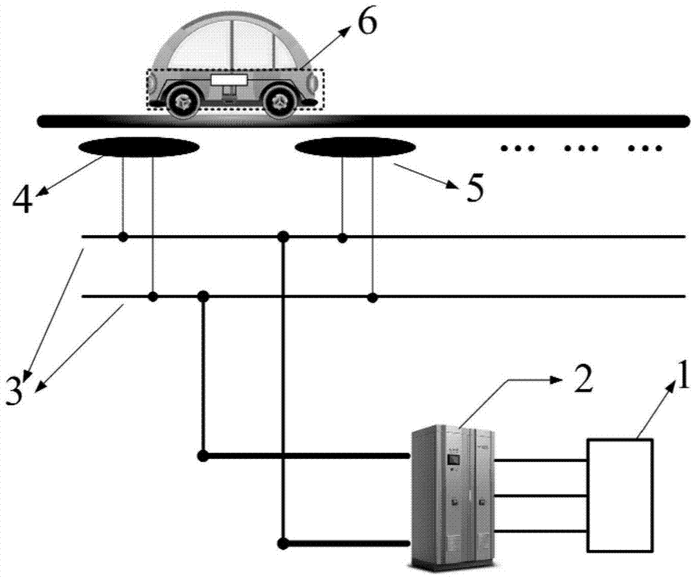
[0025] figure 1 The principle diagram of the traveling charging system for electric vehicles of the present invention is given, including a rectifier, several magnetically coupled resonant emitter groups, and vehicle-mounted resonant receivers. The grid 1 is connected to the rectifier 2 to rectify the alternating current of the grid into direct current. Multiple sets of magnetically coupled resonant emitter groups (4, 5) are connected in parallel on the DC bus 3, and are arranged at equal intervals underground on the driving road. The DC output from the rectifier passes through the DC bus 3 and is then input into the magnetically coupled resonant emitter group and sent out. , the on-board resonant receiver set on the electric vehicle receives energy for charging in the effective power transmission area.

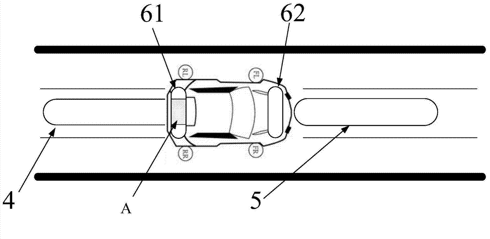
[0026] figure 2 A schematic diagram of the arrangement of the transmitting coil and the receiving coil in this embodiment is given. Each magnetically coupled resonant emit...


PUM


Abstract

The invention discloses an electric vehicle advancing type wireless charging device and control method of the electric vehicle advancing type wireless charging device. The device comprises a rectifier, several magnetic coupling resonate emitting electrode groups, and a vehicle-mounted resonate receiving electrode, wherein every magnetic coupling resonate emitting electrode group comprises a first resonate emitting electrode and a second resonate emitting electrode. The vehicle-mounted resonate receiving electrode comprises a first receiving electrode and a second receiving electrode which are separately placed at front and back ends of an electric vehicle. The section of an emitting coil of the resonate circuit is in the shape of long strip and arranged crossly; the section of a receiving coil in the vehicle-mounted resonate receiving electrode is in the shape of long strip and vertically arranged. Two receiving electrodes are under the mutual complementary state, namely, when one receiving electrode is under the high-efficient emitting scale of the magnetic coupling resonate emitting electrode, the receiving electrode is worked under the resonate power transmission state; the other one receiving electrode is under the state of compensating the receiving electrode. Through reasonable design of the structure and the control strategy, the advancing continuous high-efficient wireless charging of the electric vehicle is realized.

Description

technical field [0001] The invention relates to the research field of wireless charging technology during traveling of electric vehicles, in particular to a traveling wireless charging device for electric vehicles and a control method thereof. Background technique [0002] The existing wireless charging technology for electric vehicles can be roughly divided into two categories. One is the use of magnetic induction wireless power transmission technology. This technology applies the electromagnetic field theory described by Maxwell's equations, that is, changing electric fields will produce changing magnetic fields. The same changing magnetic field will turn into changing electric field. This technology is very sensitive to the charging distance, and requires a very short transmission distance, generally within tens of millimeters, which belongs to the transmission scheme of the air gap level, and it also has strict requirements on neutrality. Based on the above characterist...

Claims


Application Information

Patent Timeline
Patent Type & Authority Applications(China)
IPC IPC(8): H02J7/02H02J17/00B60L11/18H02J50/12
CPCH02J7/025Y02T10/72
Inventor 杨金明向如意谢兴琅
Owner SOUTH CHINA UNIV OF TECH
Learn More